6
4. Installation
Note: The Conlift lifting station must be installed in
accordance with local regulations.
• The condensate must flow freely into the lifting
station.
• The cooling slots in the motor cover must not be
covered.
• Easy access to the lifting station must be provided
to facilitate maintenance.
• The lifting station must be installed in a well-illumi-
nated and -ventilated room.
• The lifting station must be protected against
splashing water (in compliance with IP X4).
4.1 Connections
See fig. 2.
Connection for inlet hose:
Inlet opening in collecting tank, internal diameter
24 mm.
Connection for discharge hose:
Discharge stub above the built-in non-return valve,
external diameter 12 mm.
Electrical connection:
Supply cable with Schuko plug or a free cable end,
2metres.
4.2 Lifting station
The Conlift must be mounted horizontally.
The Conlift can be mounted on the floor or on the
wall.
Drilling template for the holes for wall mounting can
be found at the end of this booklet.
Depending on the type of mounting, the mounting
feet must be glued on the bottom or back of the
Conlift.
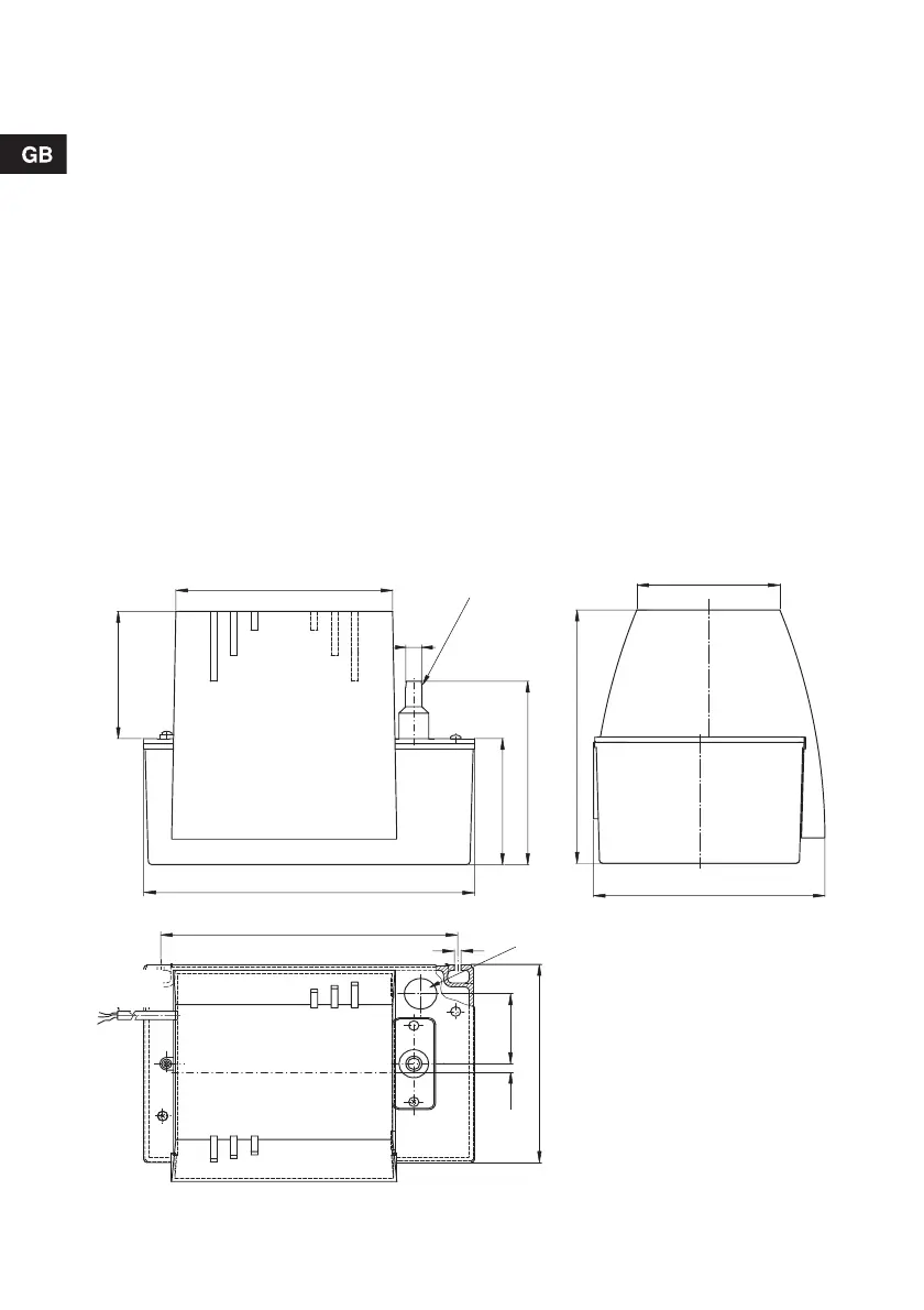
4.3 Dimensions
Fig. 2 Dimensional sketch
TM02 7496 3603
6.5
55
106
199
171
99
100
160.5
12
245
144
220
5
15
Discharge
stub
Inlet opening
Electricity
supply
 Loading...


