8
4.4 Connection of inlet and discharge
hoses
The hose supplied as an accessory can be used as
inlet and discharge hose.
• Attach the hose to the wall.
Distance between attachment points:
Approx. 30 cm.
• Make sure that the hose does not sag or is
squeezed.
• Avoid sharp bends. The bending radius of the
hose must be at least 60 mm.
• Run the inlet and discharge hoses in such a way
that they do not strain the Conlift.
4.4.1 Inlet hose
• When running the inlet hose from the boiler or
cooling/air-conditioning system to the Conlift,
make sure that the condensate flows freely into
the collecting tank.
• Insert the inlet hose sufficiently deep into the tank
through the inlet opening, see fig. 7. It is recom-
mended to make a sloping cut to the hose.
4.4.2 Discharge hose
• Pass the discharge hose end over the discharge
stub (the grommet should not be lubricated with
grease), see fig. 7. Fasten the hose with the
clamp supplied with the lifting station.
• Take the discharge hose vertically up to the high-
est point from where the condensate can flow
freely into the sewage system or drain of the build-
ing.
• If the Conlift is positioned below sewer level, the
hose must have a return loop at the highest point.
The lower edge of the loop must be 10 to 20 cm
above sewer level (the sewer level usually corre-
sponds to the street level).
• At the highest point, a loop must be formed. The
bending radius of the hose must be at least
60 mm.
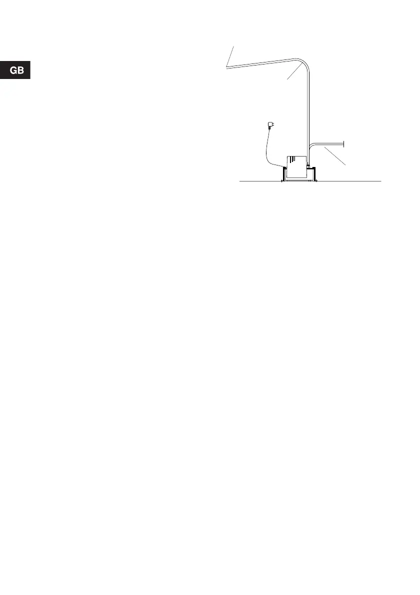
Fig. 5 Arrangement of hoses
TM02 7500 3603
R > 60 mm
R > 60 mm
Schlauchende zum
Freigefälleanschluss
R > 60 mm
Hose end to be connected to
sewage system or drain
R > 60 mm
 Loading...


