9
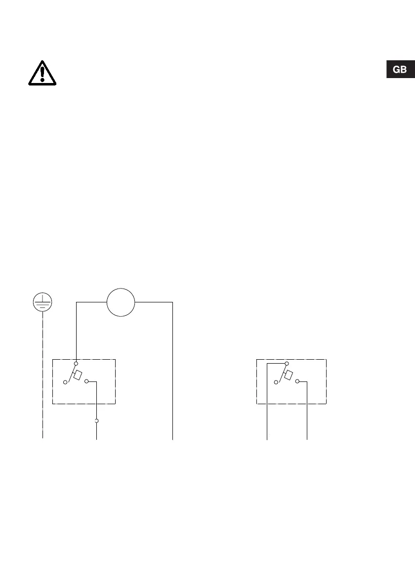
4.4.3 External alarm/potential-free contact
If the potential-free contact is used, the cable must
be run as shown in fig. 6.
Procedure:
1. Remove the screw holding the motor cover in
place (pos. 2) and lift off the cover, see fig. 8.
2. Remove all cable connections between pressure
switch 1 (pos. 9) and pressure switch 2 (pos. 10),
see fig. 8.
3. Remove the buzzer (pos. 22).
4. Connect the brown supply cable lead to terminal
3 on pressure switch 1.
5. Connect the blue supply cable lead to the motor
terminal.
6. Connect the black leads with flat plugs to termi-
nals 1 and 3 on pressure switch 2 (the leads are
not supplied with the lifting station).
7. Attach the black leads with the strain-relief.
The strain-relief and sheet metal screws are in-
cluded in the mounting kit.
8. Fit the motor cover and fasten it with the screw.
Fig. 6 Wiring diagram
Before starting work on the Conlift, the
electricity supply must be switched off. It
must be ensured that the electricity supply
cannot be accidentally switched on.
Work on electrical systems and compo-
nents must only be carried out by a quali-
fied electrician.
TM02 7501 3603
M
L1
braun
1
2
3
braun
Q
blau
PE
N
1
2
3
Q
schwarzschwarz
Option
Externer Alarm
Druckschalter 1
Pos. 9
Druckschalter 2
Pos. 10
potentialfreie Kontakte
Brown
Pressure
switch 1
Pos. 9
Pos. 9
Brown
Blue
Optional:
External alarm
Potential-free contact
Pressure
switch 2
Pos. 10
Black
Black
M
 Loading...


