10
5. Electrical connection
The electrical connection must be carried out by a
qualified electrician in accordance with local regula-
tions.
Note: Make sure that the supply voltage and fre-
quency correspond to the values stated on the
nameplate.
• Distance from the Conlift: 1 to 1.5 metres.
• The Schuko socket/socket with earth connection
and the boiler or cooling/air-conditioning system
must be connected to two different circuits. In
case of supply failure or undesired cut-out of the
cooling/air-conditioning system, this ensures that
the condensate, which continues to flow into the
collecting tank, is pumped away, thus causing no
damage.
• The Conlift incorporates a thermal switch, which
stops the motor in case of overload. When the mo-
tor has cooled to normal temperature, it will restart
automatically.
As standard, the Conlift is fitted with an alarm device
(buzzer). It is also possible to pass on the alarm indi-
cation via a potential-free contact.
See section 4.4.3 External alarm/potential-free con-
tact.
6. Start-up
Note: Start-up of the Conlift must be made in ac-
cordance with local regulations and accepted codes
of good practice.
1. Make sure that all hoses and connections are
tight.
2. Make sure that the motor cover (pos. 2) is
screwed on the Conlift, see section 8. Compo-
nents.
3. Switch on the electricity supply.
6.1 Checking the function
Pump operation:
Procedure:
1. Cut off the flow of condensate from the boiler or
cooling/air-conditioning system, or stop the flow
of condensate to the Conlift.
2. Pour the liquid of the collecting tank into a suita-
ble container.
3. Pull the inlet hose out of the collecting tank.
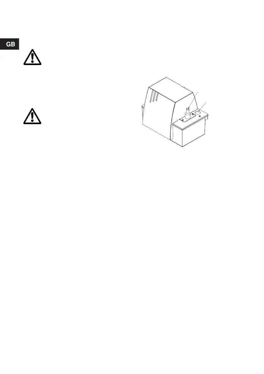
Fig. 7 Discharge stub and inlet opening
4. Pour approx. 1.7 litres of water into the collecting
tank through the inlet opening until the start level
is reached and the pump is started via pressure
switch 1.
5. Stop pouring water into the tank.
When the stop level is reached, the pump must
stop.
For stop/start/alarm levels, see fig. 1, section 3.
Function.
Alarm:
Continue the procedure:
6. To ensure that the alarm level is reached,
squeeze the discharge hose (or close the isolat-
ing cock, if any), and pour approx. 1.5 litres of
water into the collecting tank.
The pump is started via pressure switch 1.
7. Continue to pour water into the tank until the
alarm pressure switch (pressure switch 2) cuts
out. The buzzer is activated.
Note: The alarm pressure switch must release
the alarm (buzzer) before the water starts to run
out of the Conlift.
For stop/start/alarm levels, see fig. 1, section 3.
Function.
8. Stop pouring water into the tank and stop
squeezing the discharge hose. The alarm
(buzzer) stops. The pump continues to run.
When the stop level is reached, the pump stops.
Before starting work on the Conlift or
moving the Conlift, the electricity supply
must be switched off. It must be ensured
that the electricity supply cannot be
accidentally switched on.
As a precaution, the Conlift must be con-
nected to a Schuko socket or a socket with
earth connection.
It is recommended to fit the permanent in-
stallation with an earth leakage circuit
breaker (ELCB) with a tripping current
< 30 mA.
The Conlift must be connected to an exter-
nal mains switch with a minimum contact
gap of 3 mm in all poles.
TM02 7502 3603
Druckanschluss
Außen - ø10 mm
Zulaufanschluss
Innen - ø24 mm
Inlet opening
internal ø24 mm
Discharge stub
external ø12 mm
 Loading...


