7. To renew the thrust-handling-device wear parts, see the section
on renewing thrust-handling-device wear parts.
Related information
3.1.1 Removal
3.2.2 Dismantling
4. Renewing thrust-handling-device wear parts
3.3.2 Assembly
1. Install the flange (120k) in the pump base (6).
2. Fit and tighten the four screws (26b).
3. Fit the stationary ring (120g) together with the lifting plate (120h)
by using service tool G.
4. Fit thrust-handling device parts (120a,120b, 120c, 120d).
5. Fit the washer (120e) and nut (120f).
6. Tighten the nut (120f).
Note: Left-hand thread.
7. Follow the assembly instructions described in the section on
shaft seal, motor stool, pump head cover, sleeve and chamber
stack assembly.
Related information
3.2.3 Assembly
7.1 Torques
7.3.1 Special tools
3.3.3
Servicing the thrust-handling device from the pump base
Preparations
1. Disconnect the power supply and remove the power cable.
2. Close the isolating valves, if fitted, to avoid draining the pipe
system.
3. Drain the pump by opening the vent screw (18) and removing
the plugs (25) with O-rings (38).
4. Secure the pump with approved lifting equipment.
5. Loosen the pipe connections to the pump.
6. Loosen the base-plate bolts.
7. Place the pump horizontally with adequate work space around
the pump base (6). Follow the lifting instructions supplied with
the pump.
8. Make sure that the pump cannot move when working on it. See
the figure below.
TM071748
Inserting wedges for the pump not to move when working on it
Dismantling
1. Loosen and remove bolts (26b) from the pump base (6).
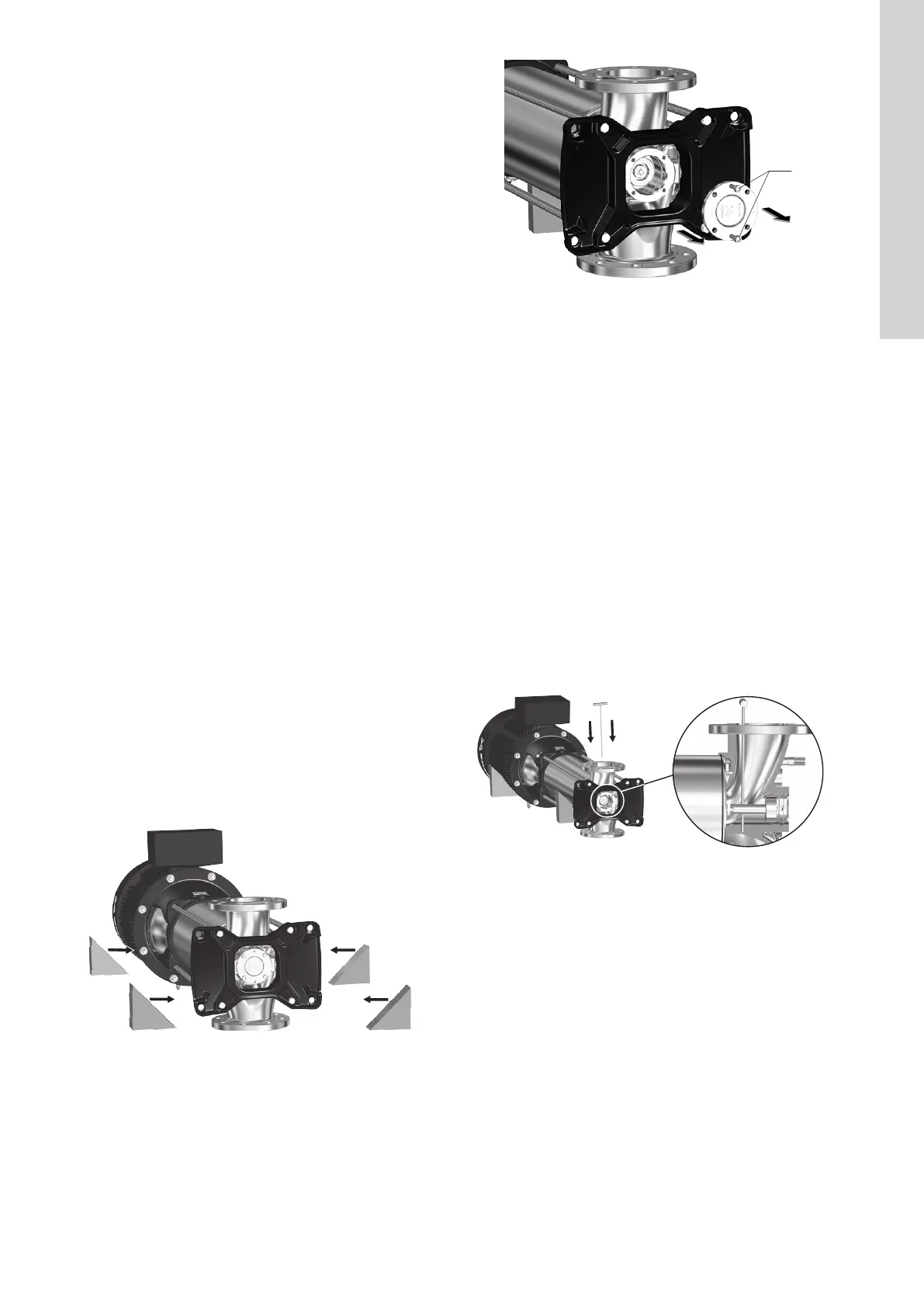
2. Remove the flange (120k) by using two bolts (26b) as
extractors. See the figure below.
TM071749
Extracting the flange
3. Pull out thrust-handling-device wear parts (120g, 120h). You can
use service tool G for this.
4. Loosen and remove the nut (120f) and washer (120e). Note that
the nut features a left-handed thread. Use service tool D to hold
the pump shaft (51) when loosening. For information on holding
the pumps shaft (51) with service tool D, see the section on
assembly.
5. Pull out thrust-handling-device parts (120a, 120b, 120c, 120d).
The parts come out together.
6. To renew the thrust-handling-device wear parts, see the section
on renewing thrust-handling-device wear parts.
Related information
3.3.4 Assembly
4. Renewing thrust-handling-device wear parts
3.3.4
Assembly
1. Fit thrust-handling-device parts (120a, 120b, 120c, 120d).
2. Fit the washer (120e) and nut (120f).
3. Tighten the nut (120f). Use service tool D to hold the pump shaft
(51) when tightening. See the figure below.
Note that the nut features a left-handed thread.
TM071895
Holding the pumps shaft (51) with service tool D.
4. Lubricate the stationary ring (120g) on the sides only, and avoid
lubrication of the seal face.
5. Install the lifting plate (120h) in the stationary ring (120g).
6. Install the stationary ring (120g) with lifting plate (120h) in the
flange (120k).
7. Fit the stationary ring (120g) together with the lifting plate (120h)
in the flange (120k).
8. Install the flange (120k) in the pump base (6).
9. Fit and tighten the four bolts (26b).
Related information
7.1 Torques
11
English (GB)
 Loading...


