English (GB)
10
4.1.1 Servicing the chamber stack in service tool for vice
mounting
Preparations
Removing the chamber stack requires that the pump has been
dismantled as described in the following sections:
• 3.1.1 Removal.
• 3.2 Shaft seal, motor stool, pump head cover, sleeve and
chamber stack.
• 3.3 Thrust-handling device.
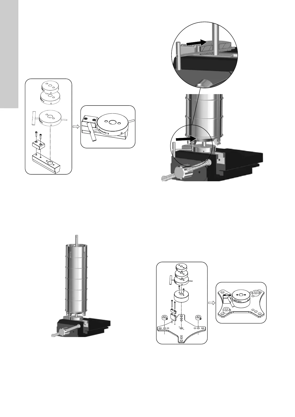
• Assemble service tool H1. See fig. 17.
Fig. 17 Service tool H1
Procedure
1. Place service tool H1 securely in a vice. See fig. 18 for correct
positioning.
2. Fit service tool B in the end of the pump shaft (51).
3. Attach approved lifting equipment to service tool B and lift the
chamber stack out of the pump base (6).
4. Lift the chamber stack onto service tool H1. See fig. 18. Make
sure the pump-shaft end engages with the service tool.
Fig. 18 Positioning the chamber stack in service tool H1
5. Align the hole in the pump shaft with the hole in service tool
H1 marked "Dismantling". See fig. 18.
6. Fit service tool D in the hole marked "Dismantling".
Fig. 19 Locking the shaft in service tool H1.
7. Continue to section 4.1.3 Dismantling the chamber stack.
4.1.2 Servicing the chamber stack in service tool for pump
base mounting
Preparations
Removing the chamber stack requires that the pump has been
dismantled as described in the following sections:
• 3.1.1 Removal.
• 3.2 Shaft seal, motor stool, pump head cover, sleeve and
chamber stack.
• 3.3 Thrust-handling device.
• Assemble service tool H2. See fig. 20.
Fig. 20 Service tool H2
TM07 1902 2318TM07 1750 2218
TM07 1751 2218TM07 1903 2318
 Loading...


