English (GB)
11
Procedure
1. Fit service tool B in the end of the pump shaft (51).
2. Attach approved lifting equipment to service tool B and lift the
chamber stack out of the pump base (6).
3. Lay down the chamber stack on a solid working surface and
take the necessary precautions to prevent the chamber stack
from moving around.
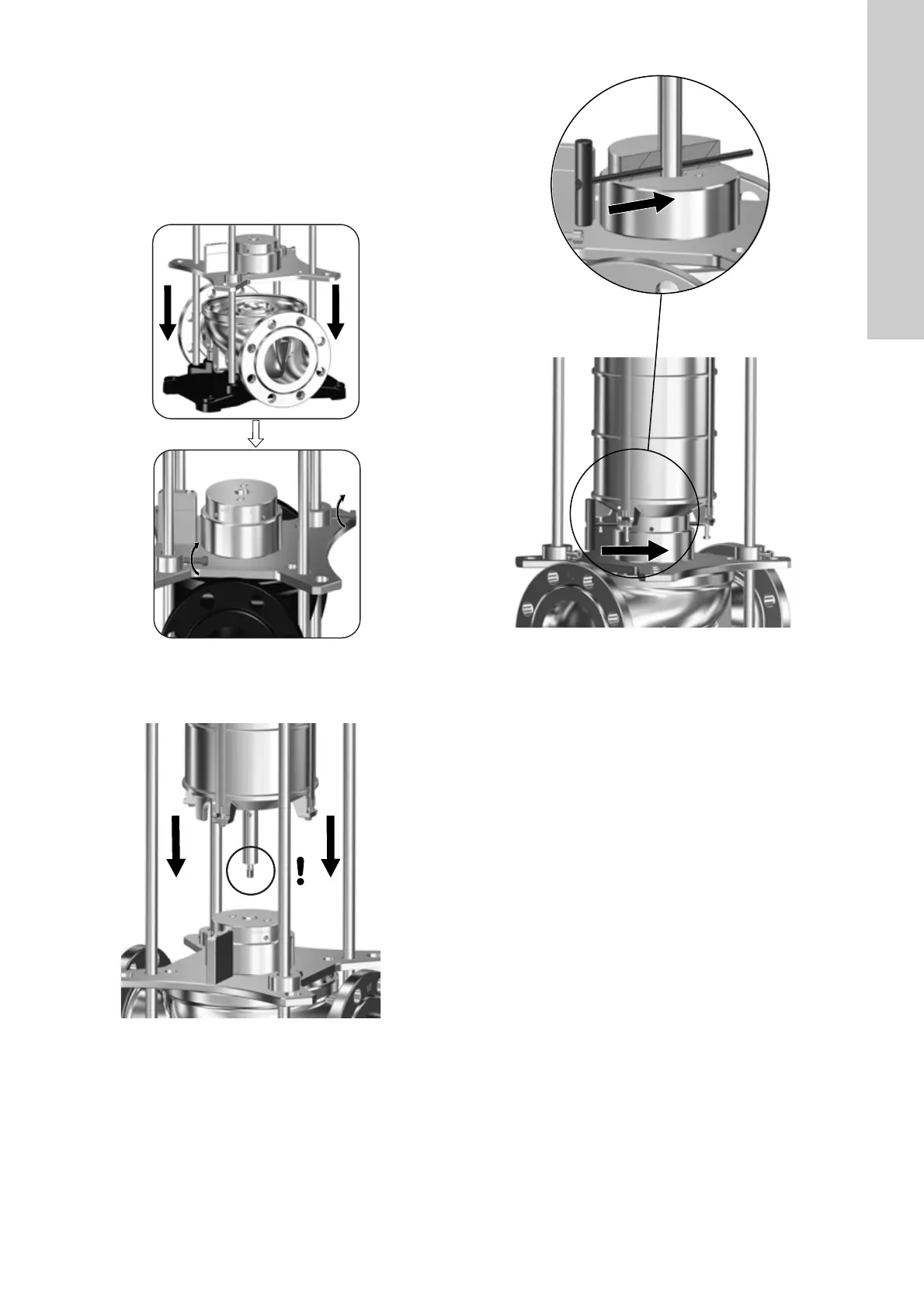
4. Install service tool H2 securely on the pump base (6). See fig.
21 for correct positioning and installation.
Fig. 21 Service tool H2 for mounting on pump base
5. Lift the chamber stack onto service tool H2. See fig. 22. Make
sure the pump-shaft end engages with the service tool.
Fig. 22 Positioning the chamber stack in service tool H2
6. Align the hole in the pump shaft with the hole in service tool
H2 marked "Dismantling". See fig. 23.
7. Fit service tool D in the hole marked "Dismantling". See fig.
23.
Fig. 23 Locking the shaft in service tool H2
8. Continue to section 4.1.3 Dismantling the chamber stack.
4.1.3 Dismantling the chamber stack
Preparations
Removing the chamber stack requires that the pump has been
dismantled as described in the following sections:
• 3.1.1 Removal.
• 3.2 Shaft seal, motor stool, pump head cover, sleeve and
chamber stack.
• 4.1.1 Servicing the chamber stack in service tool for vice
mounting or section 4.1.2 Servicing the chamber stack in
service tool for pump base mounting.
Dismantling the chamber stack also requires that it is mounted in
service tool H1 or H2 as described in sections 4.1.1 Servicing the
chamber stack in service tool for vice mounting or 4.1.2 Servicing
the chamber stack in service tool for pump base mounting.
TM07 1777 2218TM07 1752 2218
TM07 1778 2218
 Loading...


