English (GB)
12
Procedure
1. Loosen the screws (26 b) and remove the straps (26a).
2. Remove the top chamber (3 or 3a).
3. Loosen the split-cone nut (48) using service tool C, but leave
it so that it is still engaged with a few turns of thread on the
impeller (49 or 49a).
4. Install service tool I on top of the pump shaft (51) to protect
the shaft recess. Note that this applies only if the top of the
pump shaft has a reduced diameter compared to the rest of
the shaft.
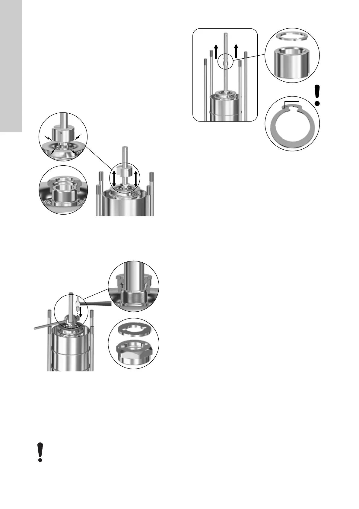
5. For pumps with ∅22 pump shaft: Turn service tool C around
and knock it against the split-cone nut (48) to loosen the
impeller (49 or 49a) from the split-cone (49b). See fig. 24.
Fig. 24 Loosening the impeller (49 or 49a) with service tool C
6. For pumps with ∅28 or ∅38 pump shaft: Insert service tool
M on top of the split-cone nut (48) and use a hammer to knock
service tool Q against the split-cone nut (48) to loosen the
impeller (49 or 49a) from the split cone (49b). See fig. 25.
Fig. 25 Loosening the impeller (49 or 49a) with service tool Q
7. Remove the split-cone nut (48), split cone (49b) and impeller
(49 or 49a).
8. Continue removing the remaining chambers (4 or 4a),
split-cone nuts (48), split cones (49b), impellers (49 or 49a)
and bearings (47a).
For pumps with ∅28 or ∅38 pump shaft:
Note that for pumps with ∅28 or ∅38 pump shaft, you must
also remove the lock ring (47g). See fig 26.
Fig. 26 Maximum permissible opening of lock ring (47g)
9. Remove the inlet part (44).
10. To renew the chamber wear parts, see section 5. Renewing
chamber wear parts.
TM07 1779 2218TM07 1780 2218
Do not open the lock ring (47g) further than the
restriction of the integrated locking mechanism. See
fig 26.
TM07 2074 2618
 Loading...


