English (GB)
5
6. CR, CRI, CRN 1, 3, 5
6.1 Dismantling
1. Remove screws (pos. 7a) and coupling guards (pos. 7).
2. Remove screws (pos. 9), coupling (pos. 8) and shaft pin
(pos. 10a).
3. Remove screws (pos. 28) and the motor.
4. Slacken socket screws (pos. 113) and remove shaft seal
(pos. 105).
5. Remove nuts (pos. 36).
6. CR: Remove motor stool (pos. 2) and O-ring (pos. 37b).
CRI, CRN: Remove motor stool (pos. 2), pump head cover
(pos. 77) and O-ring (pos. 37b).
7. Slacken socket screws (pos. 113) and remove lower shaft seal
(pos. 105b).
8. Remove cover (pos. 77a).
9. Continue dismantling according to the instructions of the
standard CR pump.
6.2 Assembly
1. Fit O-ring (pos. 37a) and rubber springs (pos. 60) in cover
(pos. 77a).
2. Fit cover (pos. 77a) on the outer sleeve.
3. Lubricate shaft (pos. 51). Fit and tighten lower shaft seal (pos.
105b) in cover (77a).
4. Press the shaft home, and tighten the socket screws of lower
shaft seal (pos. 113), using the hole for air vent screw
(pos. 18a).
5. CR: Fit O-ring (pos. 37b) in motor stool (pos. 2) and fit the
stool on the cover.
CRI, CRN: Fit O-ring (pos. 37b) in pump head cover (pos. 77),
and fit the pump head cover and the motor stool on the cover.
6. Fit washer (pos. 66a) and cross-tighten nuts (pos. 36) on the
staybolts.
7. Lubricate shaft (pos. 51). Fit and tighten upper shaft seal
(pos. 105) in motor stool (pos. 2) or pump head cover
(pos. 77).
8. Lift the pump shaft to its highest position, then push it down to
half way of its lowest position, and tighten the socket screws
of the upper and lower shaft seals.
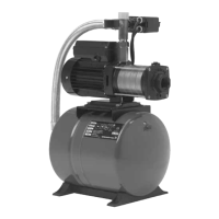
9. Lift the pump shaft, and fit the adjusting fork. See fig. 1.
Fig. 1 Fitting the adjusting fork
10. Fit the motor and tighten screws (pos. 28).
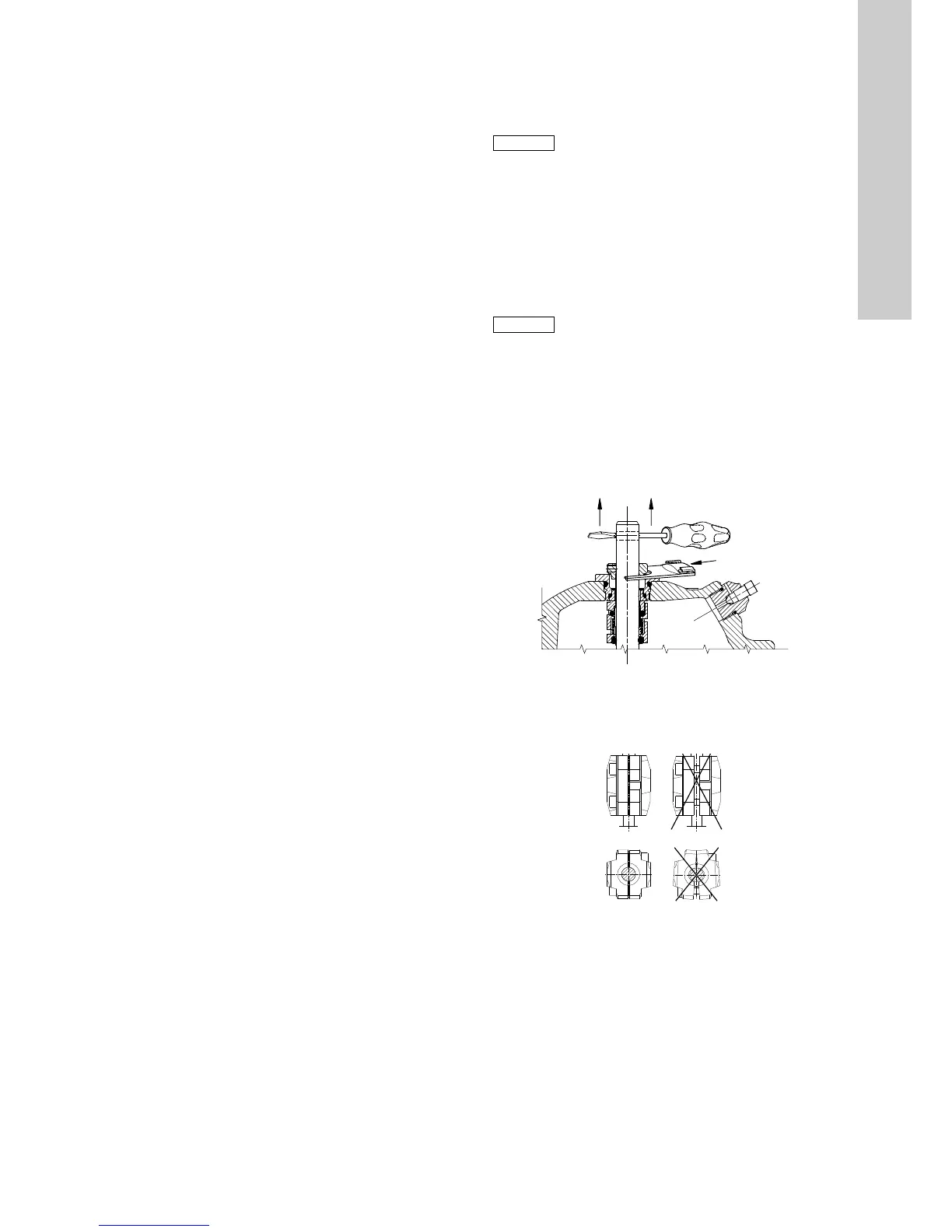
11. Fit shaft pin (pos. 10a) in the shaft, coupling (pos. 8) and
screws (pos. 9). See fig. 2.
Fig. 2 Fitting the coupling
12. Remove the adjusting fork, and place it on the inside of one of
the coupling guards (pos. 7).
13. Check that the pump shaft can rotate freely.
14. Fit coupling guards (pos. 7) and tighten screws (pos. 7a).

 Loading...