English (GB)
6
7. CR, CRI, CRN 10, 15, 20
7.1 Dismantling
1. Remove screws (pos. 7a) and coupling guards (pos. 7).
2. Remove screws (pos. 9) and the coupling.
3. Remove screws (pos. 28) and the motor.
4. Slacken socket screws (pos. 113), and remove shaft seal
(pos. 105).
5. Remove nuts (pos. 36).
6. CR: Remove motor stool (pos. 2) and O-ring (pos. 37b).
CRI, CRN: Remove motor stool (pos. 2), pump head cover
(pos. 77), and O-ring (pos. 37b).
7. Slacken socket screws (pos. 113) and remove lower shaft seal
(pos. 105b).
8. Remove cover (pos. 77).
9. Remove rubber springs (pos. 60) from underneath the cover.
10. Continue dismantling according to the instructions of the
standard CR pump.
7.2 Assembly
1. Lubricate O-ring (pos. 37a) and fit it into cover (pos. 77a).
2. Fit new rubber springs (pos. 60) underneath cover (pos. 77a)
and fit the cover on the outer sleeve.
3. Lubricate pump shaft (pos. 51). Fit and tighten lower shaft
seal (pos. 105b).
4. Press the shaft home and tighten socket screws (pos. 113) of
lower shaft seal (pos. 105b).
5. CR: Fit O-ring (pos. 37b) in motor stool (pos. 2) and fit the
stool on the cover.
CRI, CRN: Fit O-ring (pos. 37b) in pump head cover (pos. 2),
and fit the pump head cover and the motor stool on the cover.
6. Fit washers (pos. 66a) and cross-tighten nuts (36) on the
staybolts.
7. Lubricate pump shaft (pos. 51). Fit and tighten upper shaft
seal (pos. 105) in stool (pos. 2) or pump head cover (pos. 77).
8. Press the shaft home, and tighten socket screws (pos. 113) of
upper shaft seal (105).
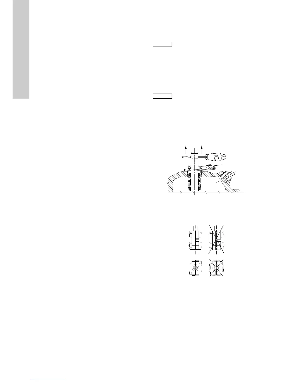
9. Lift the pump shaft, and insert the adjusting fork under the
shaft seal driver. See fig. 3.
Fig. 3 Fitting the adjusting fork
10. Fit the motor and tighten screws (pos. 28).
11. Fit shaft pin (pos. 10a) in the shaft, coupling (pos. 8) and
screws (pos. 9). See fig. 4.
Fig. 4 Fitting the coupling
12. Remove the adjusting fork, and place it on the inside of one of
the coupling guards (pos. 7).
13. Check that the pump shaft can rotate freely.
14. Fit coupling guards (pos. 7) and screws (pos. 7a).

 Loading...