English (GB)
9
16. Turn the motor and motor stool (pos. 1a) to the required
terminal box position, according to the installation
instructions.
17. Cross-tighten screws (pos. 28).
18. 55-75 kW: Fit washers (pos. 66a) and cross-tighten nuts
(pos. 36) on the stool.
19. Lift the pump shaft with the lifting tool. See fig. 9.
Fig. 9 Lifting the pump shaft
20. Insert the adjusting fork between the shaft seal driver and
carrier. See fig. 10.
Fig. 10 Inserting the adjusting forks
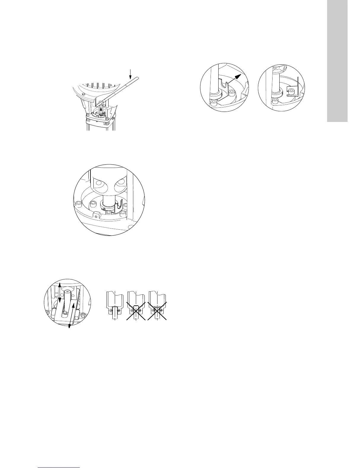
21. Fit coupling (pos. 8) on the shaft using the sliding guide or
with your hand, depending on the pump size. The top of the
pump shaft must be flush with the bottom om the clearance
chamber in the coupling. See fig. 11.
Fig. 11 Fitting the coupling
22. Lubricate and tighten screws (pos. 9), but leave loose.
23. Check that the gaps either side of the coupling halves are
equal.
24. Tighten screws (pos. 9) two and two (one side at a time).
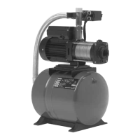
25. Remove the adjusting fork, and place it under one of the
screws (pos. 58). See fig. 12.
Fig. 12 Removing the adjusting fork and placing it under one
of the other screws
26. Check that the pump shaft can rotate freely.
27. Fit coupling guards (pos. 7) and screws (pos. 7a).
TM03 9609 4207TM03 9606 4207TM03 9607 4207
TM03 9614 4207

 Loading...