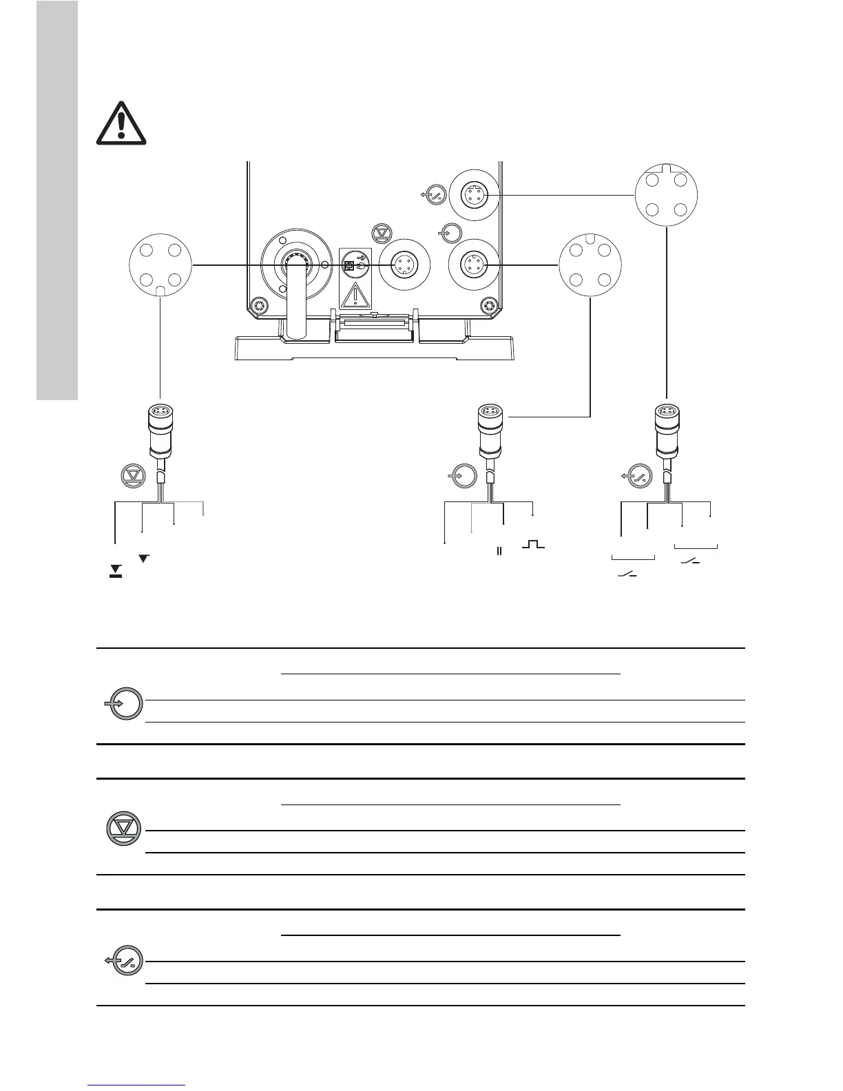
EasyManuals Logo

Grundfos DDE User Manual

Grundfos DDE
20 pages
To Next Page IconTo Next Page
To Previous Page IconTo Previous Page
Page #13 background imageLoading...
Page #13 background image
English (GB)
16
Signal connections
Applies to DDE-PR/P control variant.
Fig. 8 Wiring diagram of the electrical connections (DDE-PR/P)
External stop and pulse input
Level signals: empty and low-level signal
Relay outputs*
* applies to DDE-PR control variant
Warning
Electric circuits of external devices connected to the pump inputs must be separated from
dangerous voltage by means of double or reinforced insulation!
TM04 8172 5111
1
3
4
2
3
4
1
2
1
3
2
1
GND
GND
12
34
34
12
12
34
Function
Pins
Plug type
1/brown 2/white 3/blue 4/black
External stop GND X Pulse
Pulse GND X Pulse
Function
Pins
Plug type
1234
Low-level signal X GND Pulse
Empty signal X GND Pulse
Function
Pins
Plug type
1/brown 2/white 3/blue 4/black
Relay 1 (Alarm) X X Pulse
Relay 2 (selectable) X X Pulse

Questions and Answers:

Question and Answer IconNeed help?

Do you have a question about the Grundfos DDE and is the answer not in the manual?

Grundfos DDE Specifications

General IconGeneral
Pump TypeDiaphragm Dosing Pump
Protection ClassIP65
Control TypeManual
Power Supply230 V, 50/60 Hz
MaterialPVDF, PTFE, Ceramic
Operating Temperature0 - 40 °C
ApprovalsCE
Ambient Temperature0 - 40 °C
Dosing Accuracy< +/- 1 %

Related product manuals