14
8. Installation
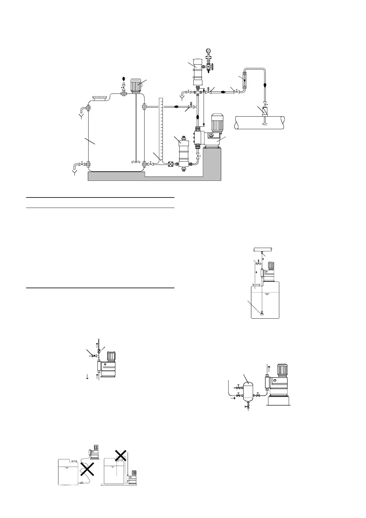
8.1 Optimum installation
Fig. 3 Example of optimum installation
8.2 Installation tips
• For easy deaeration of the dosing head, install a ball valve
(11i) with bypass line (back to the dosing tank) immediately
after the discharge valve.
• In the case of long discharge lines, install a non-return valve
(12i) in the discharge line.
Fig. 4 Installation with ball valve and non-return valve
• When installing the suction line, observe the following:
– Keep the suction line as short as possible. Prevent it from
becoming tangled.
– If necessary, use swept bends instead of elbows.
– Always route the suction line up towards the suction valve.
– Avoid loops which may cause air bubbles.
Fig. 5 Installation of suction line
• For non-degassing media with a viscosity similar to water, the
pump can be mounted on the tank (observe the maximum
suction height).
• Flooded suction preferred.
• For media with a tendency to sedimentation, install the suction
line with filter (13i) so that the suction valve remains a few
millimetres above the possible level of sedimentation.
Fig. 6 Tank installation
• Note for suction-side installation: In dosing systems with a
suction line longer than 1 metre, depending on the dosing flow,
it may be necessary to install a properly sized pulsation
damper (4i) immediately before the pump suction valve.
Fig. 7 Installation with suction-side pulsation damper
TM03 6296 4506
1i
2i
3i
4i
5i
6i
9i
10i
8i
max. 1m
16i
7i
Max. 1 m
Pos. Components
1i Dosing tank
2i Electric agitator
3i Extraction device
4i Suction pulsation damper
5i Dosing pump
6i Relief valve
7i Pressure-loading valve
8i Pulsation damper
9i Measuring glass
10i Injection unit
TM03 6297 4506TM03 6298 4506
11i
12i
TM03 6299 4506TM03 6300 4506
p
10i
6i
13i
4i
 Loading...