English (GB)
11
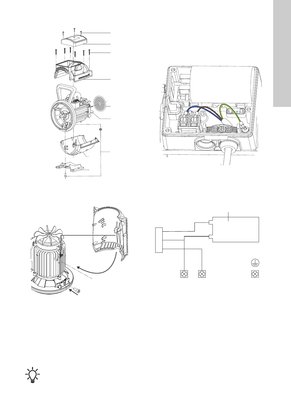
6.5 Fitting the motor shell
Fig. 26 Fitting the motor shell
1. Place the pump in a vertical position with the motor fan (14)
facing upwards.
Fig. 27 Fitting the nut and the lower motor shell
2. Place the nut (26) in the groove on the motor flange.
3. Fit the lower motor shell (42). Align the guides on the inside of
the lower motor shell (42) with the metal cooling ribs on the
stator housing. Click the motor shell in place.
4. Mount the foot (56) and tighten the screw (26).
Torque: 12 ± 1 Nm.
5. Fit the shell grid (43) in the groove in the motor shell (42).
6. Fit the upper motor shell (44).
7. Fasten the six screws (45) that hold the motor shells together.
Torque: 1.5 ± 0.1 Nm.
8. If the power cable is connected to the terminal box, fit the top
lid on the terminal box and fasten the three screws. If not,
follow the instructions below on how to connect the power
cable.
6.6 Connecting the power cable in the terminal box
1. Locate the power-supply terminal and cable clamp inside the
terminal box.
Fig. 28 Connecting the power cable to the terminal box
2. Loosen the cable clamp.
3. Push one end of the cable through the cable gland located on
the side of the terminal box.
4. Connect the cable conductors to the power-supply terminal.
See wiring diagram.
Fig. 29 Wiring diagram for the JP pump
5. Tighten the terminal screws. Torque: 2.2 ± 0.2 Nm.
6. Tighten the cable clamp screw. Torque: 1.5 ± 0.1 Nm. Make
sure not to overtighten the cable clamp screw.
7. Fit the cover (52) onto the terminal box and fasten the three
screws (53). Torque: 1.5 ± 0.1 Nm.
TM07 3814 0519TM07 3829 0519
Verification of assembly:
Turn the shaft by rotating the impeller (19) clockwise
and check that the motor fan (14) does not touch the
motor shell (42 and 44).
TM07 3836 0519TM07 3837 0319

 Loading...