English (GB)
5
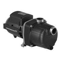
4. Mounting the handle
1. Fit the handle (190) on the motor flange.
Fig. 1 Mounting the handle
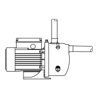
2. Place each screw (190b) with the washer on top and the
hexagon nut at the bottom.
Fig. 2 Fastening the screws on the handle
5. Dismantling the product
5.1 Before dismantling the product
• Disconnect the power supply to the motor.
• Remove the power cable in accordance with local regulations.
• Gradually loosen the valves to release the pressure in the
pump.
• Remove the drain plug (31) to drain the pump.
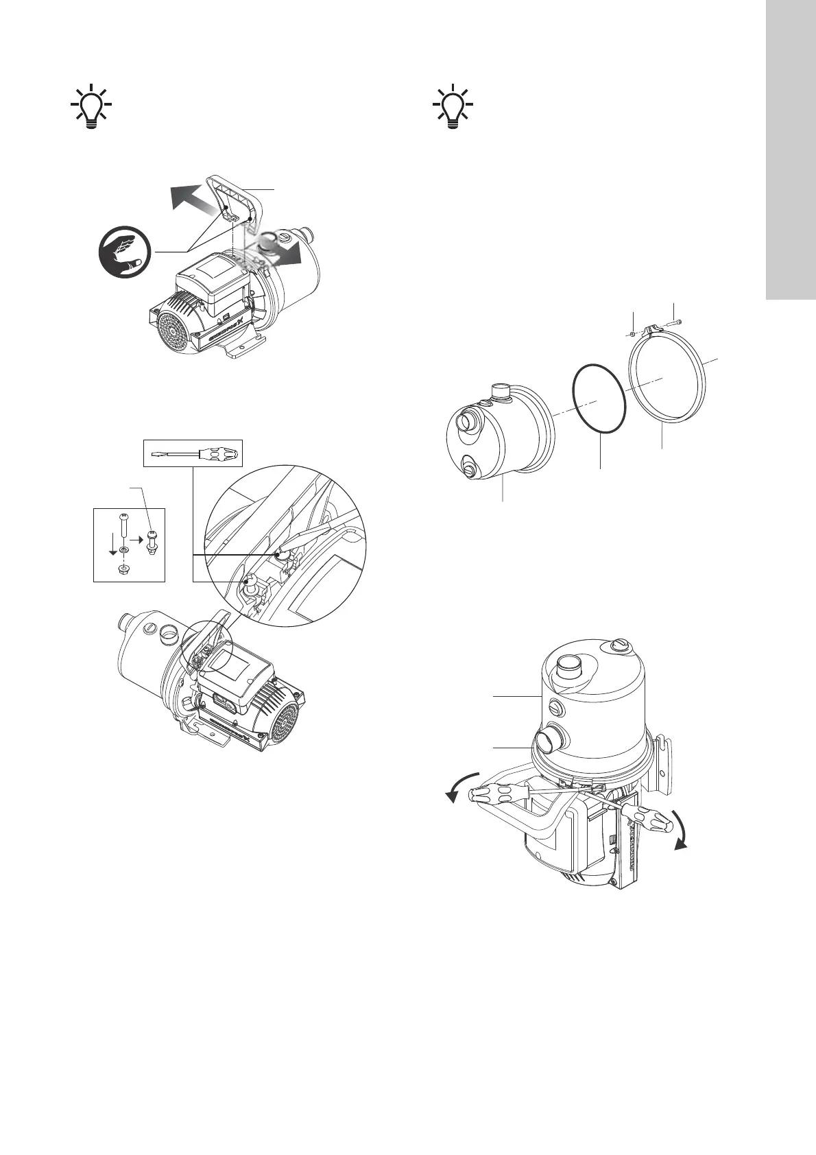
5.2 Dismantling the pump housing
Fig. 3 Dismantling the pump housing
1. Place the pump vertically with the inlet facing upwards.
2. Unscrew the clamp ring (92) by loosening screw (93) and nut
(94).
3. Remove the clamp ring (92) from the recess. Use two flat
screw drivers to lift the clamp ring from the recess.
Fig. 4 Removing the clamp ring
4. Remove the pump housing (1) including the hydraulic parts
(20 and 21).
5. Remove the O-ring (28).
Position numbers of parts (numbers in brackets) refer
to section 7.6 Exploded view.
TM07 3807 0519TM07 3834 0519
Position numbers of parts (numbers in brackets) refer
to section 7.6 Exploded view.
TM07 3808 0519TM07 3809 0519

 Loading...