EasyManuals Logo

Grundfos JP Service Instructions

Grundfos JP
16 pages
To Next Page IconTo Next Page
To Previous Page IconTo Previous Page
Page #8 background imageLoading...
Page #8 background image
English (GB)
8
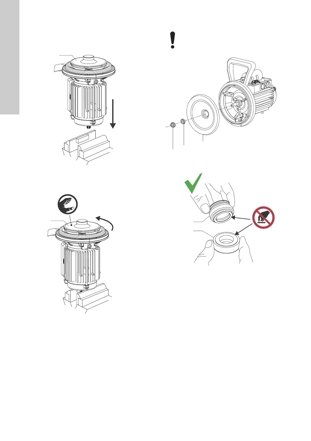
5.8 Removing the impeller
1. Place the motor vertically with the impeller (19) facing
upwards.
2. Clamp the motor shaft end in a vice with soft copper or
aluminium jaw faces to protect the shaft end.
Fig. 12 Placing the motor shaft in a vice
3. Turn the impeller (19) counterclockwise by hand and remove
it.
Fig. 13 Removing the impeller
5.9 Removing the shaft seal
Fig. 14 Shaft seal and seal disc
Fig. 15 How to correctly hold the shaft seal
TM07 3817 0519TM07 3818 0519
19
19
Do not touch the seal faces.
TM07 3819 0519TM07 3820 0519
16
16a
15
16
16a

Other manuals for Grundfos JP

Questions and Answers:

Question and Answer IconNeed help?

Do you have a question about the Grundfos JP and is the answer not in the manual?

Grundfos JP Specifications

General IconGeneral
Power supplyElectric
MaterialStainless Steel, Cast Iron
Applicationspressure boosting
Pump TypeSelf-priming centrifugal pump
Horsepower1.5 HP
PhaseSingle-phase
Inlet Size1 inch
Outlet Size1 inch

Related product manuals