English (GB)
12
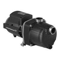
6.7 Fitting the hydraulic parts
Fig. 30 Exploded view of hydraulic parts and pump housing
1. Lubricate the O-ring seat on the diffuser (20).See section
7.1 Lubricant.
2. Fit the two O-rings (13, 21a) on the venturi tube (21).
3. Assemble the venturi tube (21) and diffuser (20) by hand.
4. Lubricate the O-ring seat inside the inlet on the pump housing
(1). See section 7.1 Lubricant.
5. Fit by hand the venturi tube (21) and diffuser (20) inside the
pump housing (1).
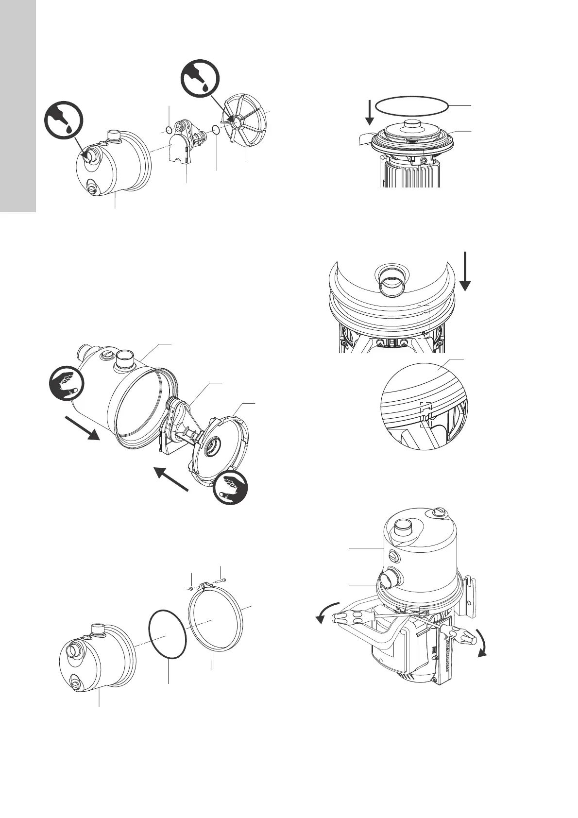
Fig. 31 Fitting the hydraulic parts in the pump housing
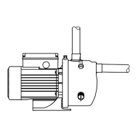
6.8 Fitting the pump housing
Fig. 32 Exploded view of the pump housing
1. Place the pump in a vertical position with the shell grid (43)
facing downwards.
2. Fit the O-ring (28) on the seal disc (15). No lubrication is
needed. Run a screw driver along the ring to remove any
twisting.
Fig. 33 Fitting the O-ring on the seal disc
3. Fit the pump housing (1) so that the cut-out on the edge of the
pump housing is aligned with the marker on the edge of the
motor flange.
Fig. 34 Aligning the pump housing on the motor flange
4. Fit the clamp ring (92) on the recess. Use two flat screw
drivers to widen the clamp.
Fig. 35 Fitting the clamp ring
5. Place the screw (93) on one side and nut and washer (94) on
the other side and tighten. Torque: 6.1 ± 0.1 Nm.
TM07 3831 0519TM07 3832 0519TM07 3808 0519
TM07 3835 0919TM07 3833 0519TM07 3809 0519

 Loading...