5
1.3 Sound pressure level
The A-weighted sound pressure level of the pump is
lower than 65 dB(A). The level has been measured
in accordance with ISO 3743 and the pump has been
suspended from two vibration-free suspension
points.
2. Electrical connection
Note: Depending on local regulations, a pump with
10 metres of mains cable must be used if the pump
is used as a portable pump for different applications.
The electrical connection should be carried out in ac-
cordance with local regulations.
The operating voltage and frequency are marked on
the nameplate. Please make sure that the motor is
suitable for the electricity supply on which it will be
used.
The pump incorporates thermal overload protection
and requires no additional motor protection.
Motors for KP 350, 3 x 200 V, 50 and 60 Hz, must be
connected to a motor starter.
If the motor is overloaded, it will stop automatically.
Three-phase pumps which are to be used with a
float switch/vertical level switch must be connected
to the mains supply via a contactor, see fig. 2.
Fig. 2
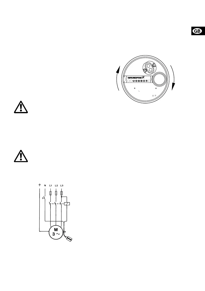
2.1 Checking of direction of rotation
(Three-phase pumps only)
The direction of rotation should be checked every
time the pump is connected to a new installation.
Check the direction of rotation as follows:
1. Position the pump on a plane surface.
2. Start and stop the pump.
3. Observe the movement of the pump (jerk). If the
pump moves as shown in fig. 3 (clockwise), the
direction of rotation is correct (counter-clock-
wise). If not, two of the supply phases to the mo-
tor should be interchanged.
Fig. 3
If the pump is connected to a piping system, the di-
rection of rotation can be checked as follows:
1. Start the pump and check the quantity of water.
2. Stop the pump and interchange two of the
phases to the motor.
3. Start the pump and check the quantity of water.
4. Stop the pump.
5. Compare the results taken under points 1 and 3,
and the connection which gives the larger quan-
tity of water is the correct direction of rotation.
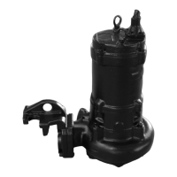
3. Installation
3.1 Connection
The discharge pipe/hose is fitted to the Rp 1¼ dis-
charge port. Steel pipes can be screwed directly into
the pump discharge port.
For permanent installation a union fitted to the dis-
charge pipe at a convenient point is recommended to
facilitate ease of removal for cleaning and servicing.
If a hose is fitted, use a screwed hose coupling.
The pipe threads or hose coupling should be sealed
using teflon sealing tape or similar material.
Note: The pump must not be installed hanging from
the discharge pipe.
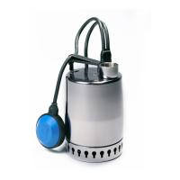
When the pump is installed in a permanent installa-
tion with float switch/vertical level switch, a non-re-
turn valve must be fitted in the discharge pipe/hose.
If the pump is installed in a well and with a minimum
free cable length according to figure 9, the minimum
dimensions of the well should be as shown in figure
4 to ensure free movability of the float switch. Figure
5 shows a pump with a vertical level switch.
Furthermore, the well should be dimensioned ac-
cording to the relation between the water flow to the
well and the pump capacity.
As a precaution, the pump must be con-
nected to a socket with earth connection.
It is recommended to fit the permanent in-
stallation with an earth leakage circuit
breaker (ELCB) with a tripping current
< 30 mA.
The pump must be connected to an exter-
nal mains switch with a minimum contact
gap of 3 mm in all poles.
When it has cooled to normal temperature,
it will restart automatically.
TM00 2011 3793
Yellow/green
Blue
Brown
Black
10 m
1
01.XX XX
P XXX W XXX A
U XXXXXXX V XX Hz
GRUNDFOS TYPE KPXXX
Made in Denmark
Ins. cl. F IP68
Hmax XXX m
3
Qmax XXXX m /h
Serial no. P1XXXXXXXXXA
TM00 2010 2593
 Loading...