8
Fig. 13
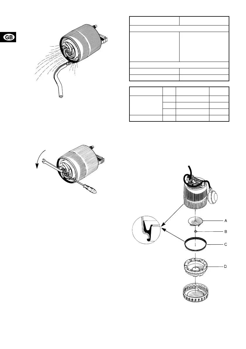
4. Check that the impeller can rotate freely. If not,
remove the impeller:
• Slacken and remove the nut on the motor shaft
(13 mm). Prevent the impeller from rotating by
means of a screwdriver, see fig. 14.
• Clean the impeller and around the shaft.
Fig. 14
5. Check the impeller, the pump housing and the
sealing part. Replace possible defective parts.
Assemble the pump in reverse order of dismantling.
Note: Check before and when fitting the pump hous-
ing that the sealing part is positioned correctly, see
fig. 15. Moisten the sealing part with water to facili-
tate the fitting.
4.2 Replacement of parts
The impeller, the pump housing and the sealing part
can be replaced.
The part numbers and the components included in
the service kits will appear from the tables below and
fig. 15.
If pump components other than those mentioned
above are damaged or defective, please contact
your pump supplier.
A possible replacement of the cable or the float
switch/vertical level switch must be carried out by an
authorised GRUNDFOS service workshop.
Fig. 15
TM00 1555 0493TM00 1556 0493
Pump type Part number
Impeller kit
KP 150, 50 Hz
KP 250, 50 Hz
KP 150, 60 Hz
KP 250, 60 Hz
KP 350, 50 Hz
KP 350, 60 Hz
01 57 78
01 57 79
01 57 83
01 57 84
01 57 85
01 57 86
Pump housing
KP 150 and KP 250 01 57 70
KP 350 01 57 71
Service kit Pos. Description Qty.
Impeller kit
A Impeller 1
BNut 1
C Sealing part 1
Pump housing D Pump housing 1
TM00 1557 2297
 Loading...