English (GB)
10
* If an external supply source is used, there must be a
connection to GND.
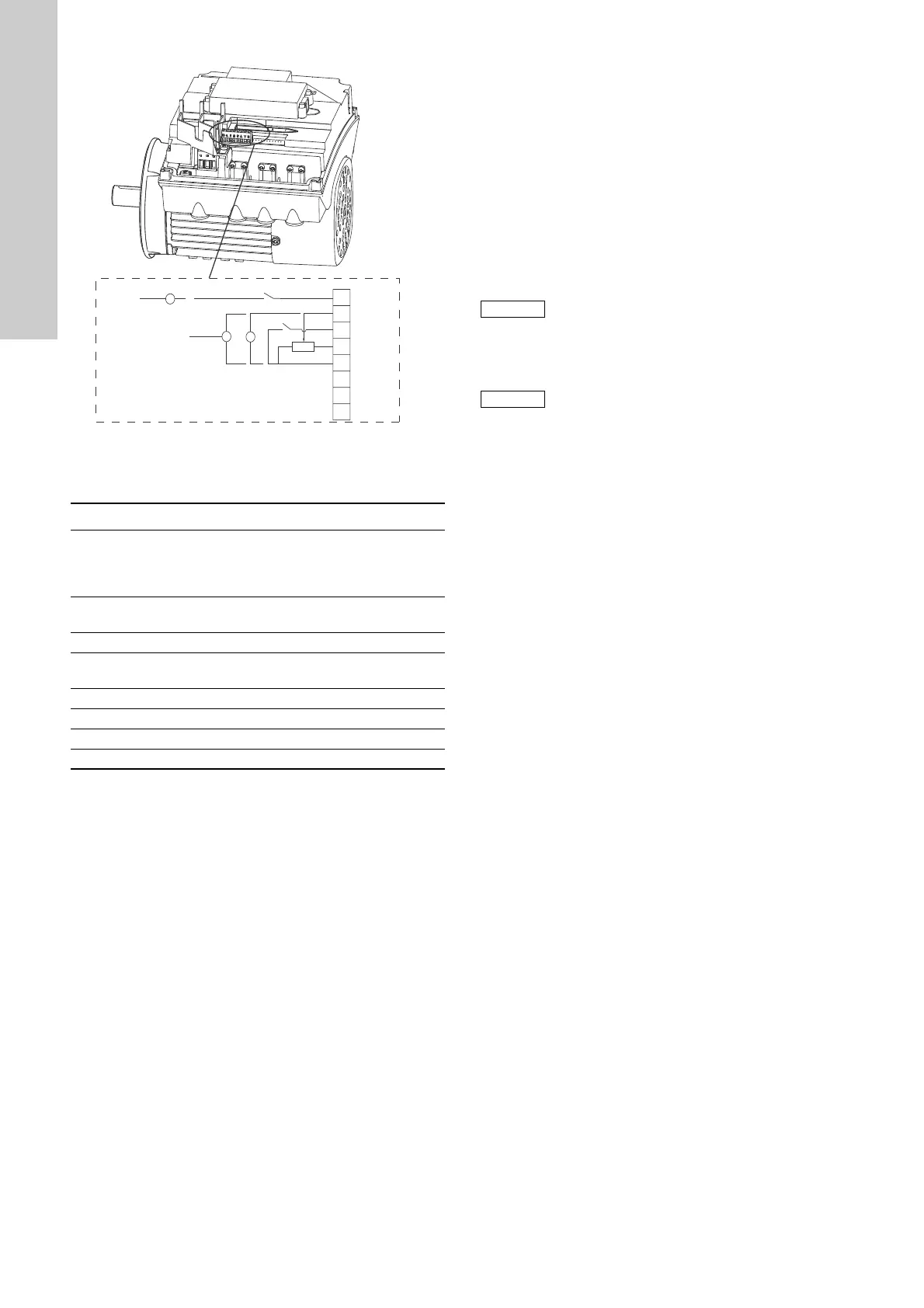
Fig. 10 Connection terminals, FM 100
6.6.2 Standard functional module (FM 200)
The FM 200 has more inputs and outputs than the FM 100 and is
suitable for even more demanding applications.
The FM 200 has these connections:
• two analog inputs
• two digital inputs or one digital input and one open-collector
output
• Grundfos Digital Sensor input and output
• two signal relay outputs
• GENIbus connection.
See fig. 11.
• Inputs and outputs
All inputs and outputs are internally separated from the
mains-conducting parts by reinforced insulation and
galvanically separated from other circuits.
All control terminals are supplied by safety extra-low voltage
(SELV), thus ensuring protection against electric shock.
• Signal relay outputs
– Signal relay 1:
LIVE:
Mains supply voltages up to 250 VAC can be connected to
this output.
SELV:
The output is galvanically separated from other circuits.
Therefore, the supply voltage or safety extra-low voltage
can be connected to the output as desired.
– Signal relay 2:
SELV:
The output is galvanically separated from other circuits.
Therefore, the supply voltage or safety extra-low voltage
can be connected to the output as desired.
• Mains supply (terminals N, PE, L or L1, L2, L3, PE).
A galvanically safe separation must fulfil the requirements for
reinforced insulation including creepage distances and
clearances specified in EN 61800-5-1.
TM05 3511 1512
Terminal Type Function
10 DI3/OC1
Digital input/output,
configurable.
Open collector: Max. 24 V
resistive or inductive.
4AI1
Analog input:
0.5 - 3.5 V / 0-5 V / 0-10 V
2 DI1 Digital input, configurable
5+5 V
Supply to potentiometer and
sensor
6 GND Ground
A GENIbus, A GENIbus, A (+)
Y GENIbus, Y GENIbus, GND
B GENIbus, B GENIbus, B (-)
B
Y
6
5
2
4
10
A
GENIbus A
GENIbus B
GENIbus Y
GND
+5 V
DI1
AI1
DI3/OC1
+24 V*
OC
DI
GND
+
+
+24 V*/5 V*
Digital input 1 is factory-set to be start/stop input
where open circuit will result in stop. A jumper
has been factory-fitted between terminals 2 and
6. Remove the jumper if digital input 1 is to be
used as external start/stop or any other external
function.
As a precaution, the wires to be connected to the
connection groups below must be separated
from each other by reinforced insulation in their
entire lengths.

 Loading...