TM028042
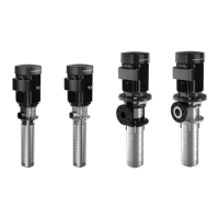
Vertical installation
Mounting flange dimensions:
Pump type
D1
*
D2
*
D3
*
L
*
C
X
*
MTR 1s, 1, 2,
3, 4, 5, 8
version A
140 160 180 100
Rp 1
1/4
G 1 1/4
∅7.5
MTR 1s, 1, 2,
3, 4, 5, 8
version I, N
140 160 180 100
Rp 1
1/4
G 1 1/4
∅9
MTR 10, 15,
20
200 225 250 125
Rp 2
G 2
∅9
MTR 32 190 220 250 150 DN 65 ∅12
MTR 45, 64 240 265 290 165 DN 80 ∅12
*
The numbers are indicated in millimetres.
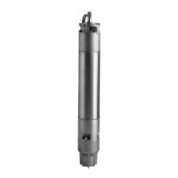
5.1.1 Inlet conditions
The bottom of the pump strainer must be at least 25
mm above the bottom of the tank.
The pumps are designed to provide full performance
down to a level of A mm above the bottom of the
strainer
.
At a liquid level between A and B mm above the
bottom of the strainer, the built-in priming screw
protects the pump against dry running.
MTR 32, 45 and 64 pumps have no priming screw.
Pump type
A
[mm]
B
[mm]
MTR 1s, 1, 2, 3, 4, 5, 8 41 28
MTR 10, 15, 20 50 25
MTR 32, 45, 64 70 -
The distance between the flange and the liquid level
must be minimum 25 mm.
The distance between the pump and the tank bottom
must be minimum 25 mm.
TM072800
MTR 1s, 1, 2, 3, 4, 5, 8
11
English (GB)
 Loading...