Do you have a question about the Grundfos Multilift MD1 and is the answer not in the manual?
Explains safety and instructional symbols used throughout the manual.
Provides warnings and instructions for safely moving the product during transport.
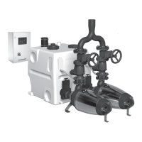
Lists all components included in the standard lifting station package.
Covers location, mechanical, and electrical installation steps for the control unit.
Details location, mechanical, and electrical installation of the lifting station.
Lists typical scenarios and building types where the product is installed.
Specifies the types of liquids suitable for pumping and those to avoid.
Describes the tank, pumps, operating modes, motor protection, level sensor, inspection cover and non-return valve.
Explains the various symbols, indicators, and readings shown on the controller's display.
Details the function of each button on the controller interface for navigation and operation.
Describes selector switches and explains the meaning of status indicator LEDs.
Outlines controller menus and lists default settings for configuration and monitoring.
Details the wiring connections for power, pumps, sensors, and alarms.
Information on available optional accessories, including drainage pumps.
Details information found on the lifting station's nameplate.
Explains how to interpret the lifting station's type designation code.
Details information found on the controller's nameplate.
Explains how to interpret the controller's type designation code.
Explains parameters like start/stop levels, delays, and maintenance intervals.
Describes how to access fault logs, counters, and motor current data.
Guides on configuring controller settings like levels, current, and delays.
Details recommended maintenance intervals based on installation type.
Covers procedures for maintaining the product's mechanical components.
Lists checks and procedures for maintaining the electrical system and components.
Troubleshooting guide for fault code F001, related to phase sequence issues.
Troubleshooting guide for fault code F002, related to missing phases.
Troubleshooting guide for fault code F003, indicating high liquid level.
Troubleshooting guide for fault codes F007 and F008, indicating pump blockages or phase issues.
Troubleshooting guide for fault code F117, related to display communication issues.
Troubleshooting guide for relay faults affecting pump start/stop operations.
Troubleshooting guide for TEMP faults, indicating pump overheating.
Troubleshooting guide for SENSOR faults, indicating issues with the level sensor.
Troubleshooting guide for EXTERN faults, related to external level switches.
Troubleshooting guide for BATT faults, indicating a discharged battery.
Detailed steps to diagnose and resolve issues where the pumps do not start.
Troubleshooting for unexpected or random pump activation.
Specifies ambient and liquid temperature limits, pH, and density.
Provides dimensions, weight, and enclosure class details.
Lists voltage, frequency, current, and fuse specifications.
| Mains frequency | 50 Hz |
|---|---|
| Enclosure class | IP68 |
| Impeller Material | Cast iron |
| Protection Class | IP68 |
| Pump type | Vortex impeller |
| Inlet connection | Flange |
| Seal Material | NBR |