5. Product description
5.1 Applications
The product is designed for the collection and pumping of wastewater with no free flow to sewer
level. Typically the product is installed below sewer level in cellars or basements in buildings such
as:
• large-scale multifamily houses
• public and commercial buildings
• blocks of flats
• schools
• offices
• hotels
• restaurants
• hospitals
• industries.
5.2 Pumped liquids
The product is designed for the collection and pumping of these liquids:
• wastewater
• sludge-containing water
• domestic wastewater containing faecal matter.
The free passage of the product enables pumping of liquids containing solids from 65 to 80 mm in
diameter, depending on the pump type.
Do not discharge these substances or types of wastewater via the product:
• Solid matter, tar, sand, cement, ash, coarse paper, paper towels, cardboard, debris, gar-
bage, grease and oil.
• Wastewater from sanitary installations situated below the backflow level must be drained
away via a free-flow drainage system according to EN 12056-1.
• Wastewater containing hazardous substances such as greasy wastewater from large-scale
catering establishments.
For drainage of greasy wastewater, use a grease separator according to EN 1825.
• Rainwater of large areas outside the building, for example parking lots, must be collected
and discharged outside the building with separate pumping stations.
Related information
• 13.1 Operating conditions
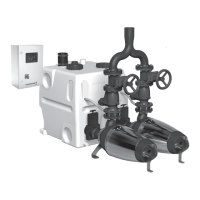
5.3 Lifting station
5.3.1 Tank
The gas-, odour- and pressure-tight tank is made of resistant polyethylene. The tank has all nec-
essary ports for the connection of inlet pipes, outlet pipe, vent pipe and a manually operated dia-
phragm pump available as an accessory.
Inside the tank the two pump connections are connected to a suction bend enabling suction from
the bottom. As a result, the residual volume is reduced to a minimum.
The table below shows the tank volume and the effective volume. The effective volume is the vol-
ume between start and stop.
Number of tanks 1 2 3
Tank volume [l] 450 900 1350
Effective volume with stop delay [l] 225 450 675
Effective volume without stop delay [l] 150 300 450
Multilift MD1, MDV | | 16