English (GB)
5
Pos. A in fig. 2:
We recommend that you install the pressure
manager so that the height between the pressure
manager and the highest tapping point does not
exceed the following values:
1.5 bar variant: 10 metres
2.2 bar variant: 17 metres.
Pos. B in fig. 2:
To achieve correct operation, the pump must at least
be able to provide the following head:
1.5 bar variant: 24 metres
2.2 bar variant: 31 metres.
Pos. C in fig. 2:
Install the pressure manager so that the operating
panel is visible and easily accessible. Make sure that
the inlet and outlet are connected correctly.
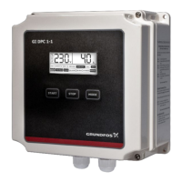
Fig. 3 Installation positions, PM 1
Pos. D in fig 2:
Do not install taps between the pump and the
pressure manager.
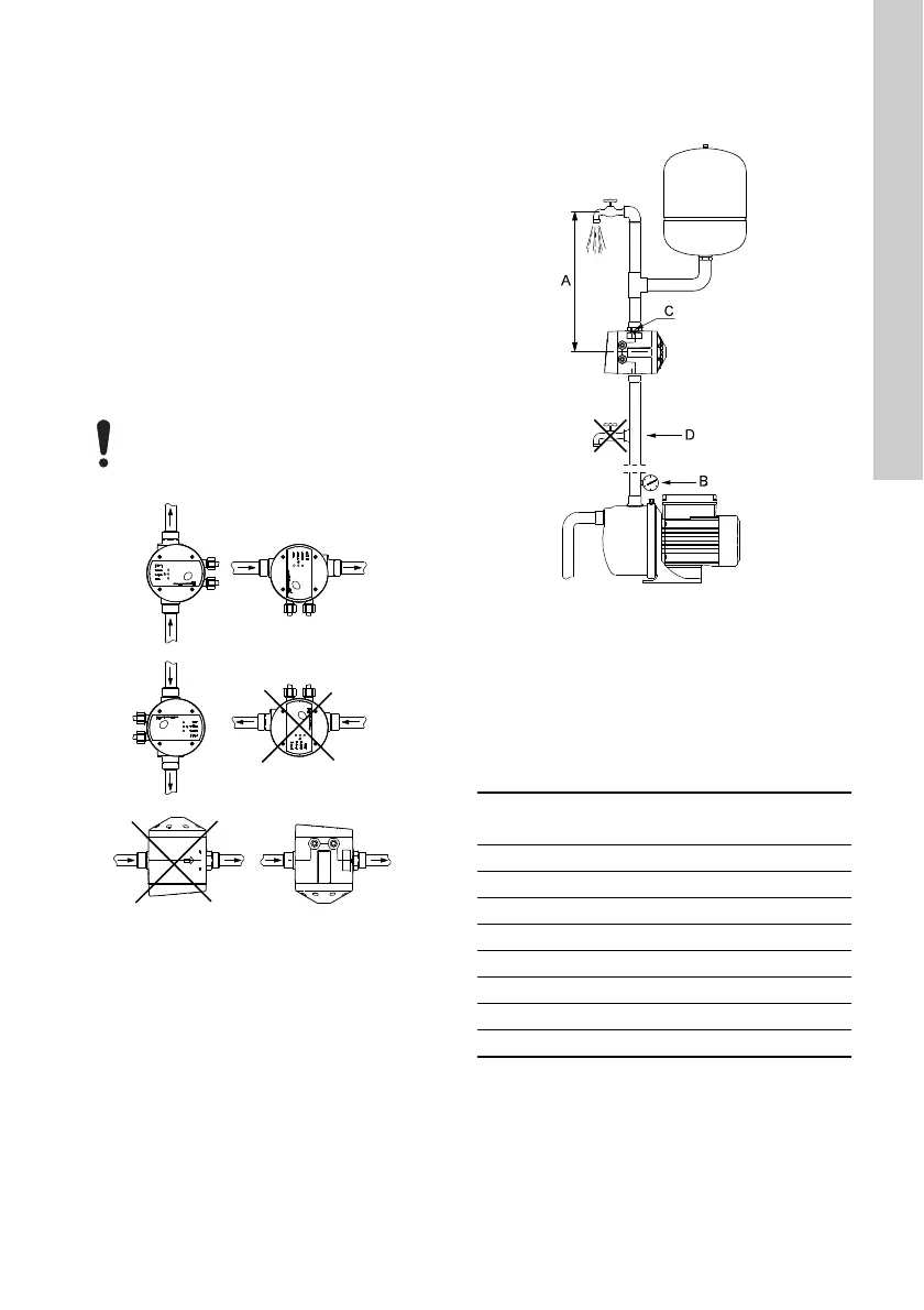
3.3 Mechanical installation, PM 2
PM 2 can be installed in systems with or without a
pressure tank. See fig. 4.
Fig. 4 Installation example
The pressure manager can be fitted directly to the
pump outlet port or between the pump and the first
tapping point.
Pos. A in fig. 4:
We recommend that you install the pressure
manager so that the height between the pressure
manager and the highest tapping point does not
exceed the values in the table below.
* Default setting.
See section 9.1 Start and stop according to water
consumption.
To prevent water from entering the
pressure manager, do not install the it so
that the cable connections are pointing
upwards. See fig. 3.
TM04 0335 1708
TM04 0336 1508
Start pressure set
[bar]
Maximum height
[m]
1.5* 11
2.0 16
2.5 21
3.0 26
3.5 31
4.0 36
4.5 41
5.0 46
 Loading...