English (GB)
7
3.4 Electrical connection, PM 1 and PM 2
• The electrical connection must be carried out in
accordance with local regulations and standards.
• The pressure manager must be connected to an
external mains switch with a contact gap of at
least 3 mm in all poles.
• As a precaution, the pressure manager must be
connected to a socket with earth connection.
• We recommend that you fit the permanent
installation with an earth leakage circuit breaker,
ELCB, with a tripping current < 30 mA.
3.4.1 Connecting pressure managers with cable
and plug fitted
Connect the pressure manager using the supplied
cable.
3.4.2 Connecting pressure managers with no
cable and plug fitted
1. Remove the operating panel of the pressure
manager.
2. Carry out the electrical connection as shown in
fig. 1 or 2 on page 35, depending on motor type.
3. Fit the operating panel securely with all four
mounting screws so that enclosure class IP65 is
maintained.
3.4.3 Alternative power supply
PM 1 and PM 2 can be powered by a generator or
other alternative power supplies, provided that the
requirements for the power supply are fulfilled. See
section 16.2 Technical data, PM 2.
4. Control functions
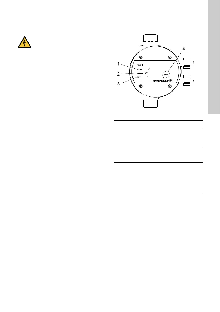
4.1 Operating panel, PM 1
Fig. 7 Operating panel, PM 1
DANGER
Electric shock
- Death or serious personal injury
- Before making any connections in the
pressure manager, make sure that the
power supply has been switched off and
that it cannot be accidentally switched
on.
TM03 9360 1708
Pos. Description Function
1"Power on"
The green indicator light is
permanently on when the
power supply has been
switched on.
2 "Pump on"
The green indicator light is
permanently on when the
pump is running.
3"Alarm"
The red indicator light is
permanently on or flashes
when the pump has
stopped due to an operating
fault.
See section 15.1 Fault
finding, PM 1.
4[Reset]
The button is used for
• resetting fault indications
• enabling and disabling of
the anti-cycling function.
See section 9.3 Power
supply failure.
 Loading...