English (GB)
8
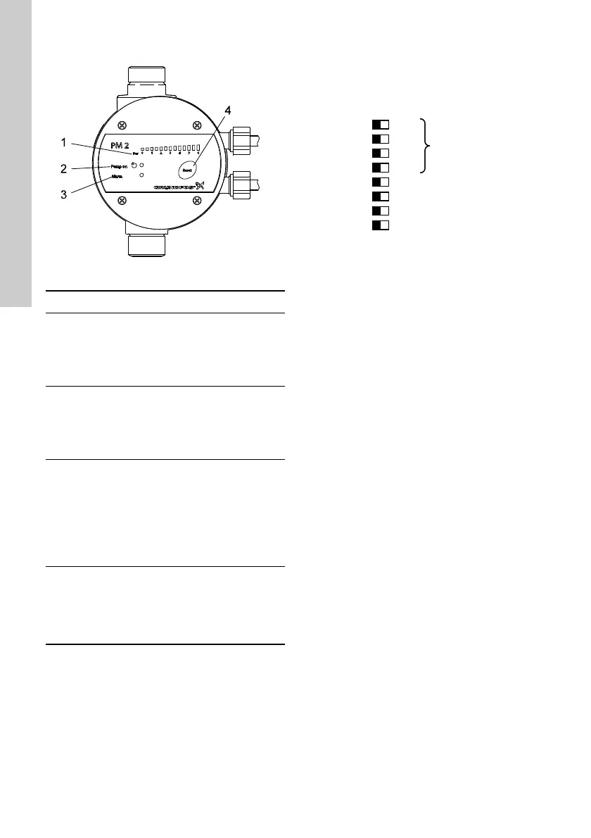
4.2 Operating panel, PM 2
Fig. 8 Operating panel, PM 2
4.2.1 DIP switches, PM 2
PM 2 has a number of settings which can be made
with the DIP switches behind the operating panel.
See fig. 9.
Fig. 9 DIP switches
TM03 9361 1508
Pos. Description Function
1
"Pressure
scale"
The pressure scale has 13
light fields indicating the
pressure from 0 to 6 bar.
All light fields illuminate
briefly when the power
supply is switched on.
2 "Pump on"
The green indicator light is
permanently on when the
pump is running.
The indicator light also
illuminates briefly when the
power supply is switched on.
3 "Alarm"
The red indicator light is
permanently on or flashes
when the pump has stopped
due to an operating fault.
See section 15.2 Fault
finding, PM 2.
The indicator light also
illuminates briefly when the
power supply is switched on.
4[Reset]
The button is used for
• resetting fault indications
• checking the DIP switch
settings.
See section 4.2.3 Checking
the DIP switch settings.
TM04 1952 1508
+1.0
+1.0
4 +1.0
5 STOP = START + 1
6 AUTO RESET
ANTI CYCLING
MAX RUN 30 MIN.
OFF/ON
START
1.5 BAR 1
2
+
+
1.0
0.5
3 +1.0
4 +1.0
5 STOP = START + 1 BAR
6
7 ANTI CYCLING
8 MAX RUN 30 MIN.
OFF/ON
START
 Loading...