English (GB)
6
Pos. B in fig. 4:
To achieve correct operation, the pump must at least
be able to provide the outlet pressures in the table
below.
Minimum outlet pressure
* Default setting.
See section 9.1 Start and stop according to water
consumption.
** See section 9.2 Start and stop with one bar
differential pressure.
Pos. C in fig. 4:
Install the pressure manager so that the operating
panel is visible and easily accessible. Make sure that
the inlet and outlet are connected correctly.
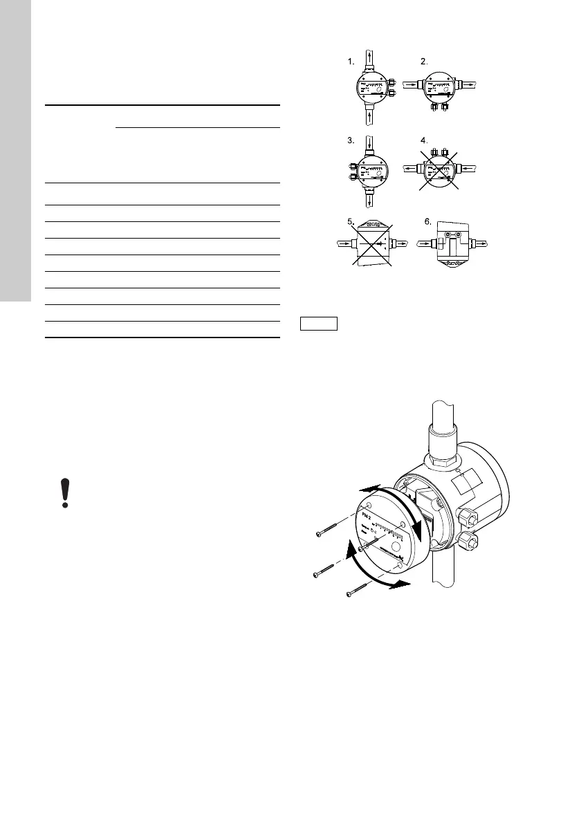
Fig. 5 Installation positions, PM 2
It is possible to loosen the operating panel and
change its position, depending on the installation
position of the pressure manager. See fig. 6.
Fig. 6 Orientation of the operating panel
Pos. D in fig. 4:
Do not install taps between the pump and the
pressure manager.
Start
pressure set
Operating mode
Start and stop
according to
water
consumption*
Start and stop
with 1 bar
differential
pressure**
[bar] [bar] [bar]
1.5* 1.9 2.9
2.0 2.4 3.4
2.5 2.9 3.9
3.0 3.4 4.4
3.5 3.9 4.9
4.0 4.4 5.4
4.5 4.9 5.9
5.0 5.4 6.4
To prevent water from entering the
pressure manager, do not install the it so
that the cable connections are pointing
upwards. See fig. 5.
TM04 1950 1708
Avoid installation position 6 if the pumped
liquid contains solid particles as these may
settle inside the internal pressure tank of
the pressure manager.
TM04 1951 1508
 Loading...