English (GB)
5
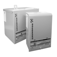
The RMQ components are shown in fig. 1.
Fig. 1 RMQ components
6. Type key
7. Technical data
7.1 Operating conditions
7.2 Dimensions
Fig. 2 Dimensional sketch (dimensions in mm)
TM04 7311 1810
Pos. Description
1 Cabinet
2Pump
3 Operating panel
4 Mains-water hose
5 Outlet hose
6 Inlet hose
7 Float valve
8 Mains-water tank
9 Emergency overflow
10 Overflow
Example RMQ 3 -45 B -A -W -A BVBP
Type range
Rated flow rate [m
3
/h]
Maximum head [m]
Code for control variant
A: Electronic controls
B: Electric control
Code for version
A: Standard
Code for pipe connection
W: Internal thread
Code for materials
A: Standard
Code for shaft seal
Flow, Q
max.
RMQ -35
RMQ -45
4.0 m
3
/h
4.5 m
3
/h
Head, H
max.
RMQ -35
RMQ -45
35 m
45 m
Liquid temperature 5-35 °C
Maximum inlet pressure,
mains-water connection
6 bar
System pressure Maximum 7.5 bar
Maximum height to highest
point of consumption
15 m
Supply voltage 230 VAC, 50 Hz
Power input during standby Approx. 2.5 W
Rated power input
RMQ -35
RMQ -45
Approx. 850 W
Approx. 1000 W
Enclosure class IP42
Ambient temperature 0-45 °C
Mounting location Indoors
Weight 24 kg
Material, cabinet EPP foam
Material, pump
Stainless steel/
POM/PPO
Material, mains-water tank PE
Dimension, mains-water hose 3/4"
Dimension, inlet and outlet
hoses
1"
Dimension, overflow DN 70
TM02 5768 0609
 Loading...