English (GB)
7
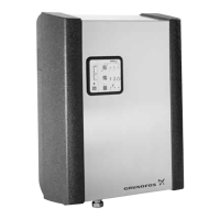
3. Before fitting a bend, if required, check that the
DN 70 pipe has a vertical fall of minimum 50 cm.
Connect the overflow to the sewage system via a
vented pipe.
Fig. 4 Overflow to sewer, example 1
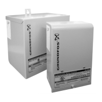
Fig. 5 Overflow to sewer, example 2
8.4 Connection of mains-water pipe
The built-in float valve is designed for a maximum
pressure of 6.0 bar.
The float valve has a simple filter in the inlet. If the
mains water is particularly dirty, we recommend that
you fit a strainer in front of the inlet to the float valve.
Fig. 6 Filter in the inlet
We recommend that you fit an isolating valve in the
fixed installation.
Procedure:
1. Connect the mains-water pipe to the mains-water
hose of the unit. See fig. 1 (4).
2. Fasten the mains-water pipe with pipe clamps.
The first hose clamp must be fitted at a maximum
distance of 10-15 cm from the unit.
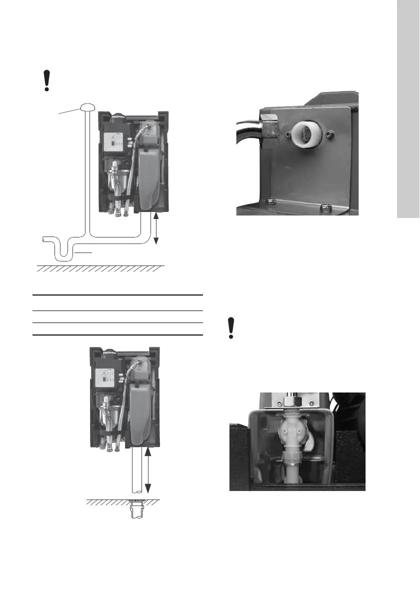
3. Check that the float valve is positioned straight in
the mains-water tank. See fig. 7.
– The float valve must be able to move freely up
and down without touching the sides of the
tank.
Fig. 7 The float valve seen from above
The RMQ overflow does not function as a
water seal.
TM04 7634 2210
Pos. Description
1 Vent cap
2 Water seal
TM04 7633 2210
TM04 6914 1110
Do not push or pull the mains-water hose;
otherwise it may cause failure of the float
valve.
TM04 6915 1110
 Loading...