English (GB)
8
8.5 Connection of inlet hose (rainwater
collecting tank)
The inlet hose must be minimum 1" (25 mm internal
diameter).
Flush the inlet hose before connecting it to the RMQ
unit. The inlet hose must be fitted with an inlet filter
(a floating inlet filter is recommended).
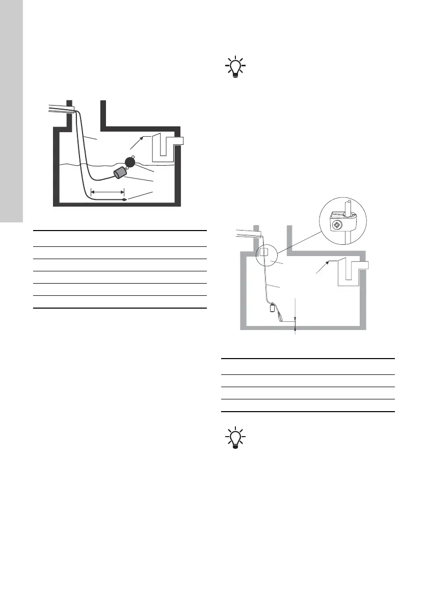
Fig. 8 Inlet hose in collecting tank
Avoid bends in the inlet hose.
The maximum suction lift of the pump can be
determined on the basis of the diagram on page 16.
Example
If the suction lift is 2.5 m, the length of the inlet hose
must not exceed 24 m.
The inlet hose must slope gradually upwards to
avoid air pockets.
Procedure
1. Connect the inlet hose to the inlet hose union.
See fig. 1 (6).
– Tighten the union without damaging the O-ring.
2. Fasten the inlet hose with hose clamps.
8.6 Connection of outlet hose
We recommend that you fit an isolating valve on the
outlet side of the pump.
Procedure
1. Connect the pump outlet hose, see fig. 1 (5), to
the water installation, such as the toilet.
2. Fasten the outlet hose with hose clamps. The
first hose clamp must be fitted at a maximum
distance of 10-15 cm from the unit.
8.7 Float switch installation (only RMQ B)
Procedure:
1. Drill a mounting hole on the inside of the tank
wall, above maximum water level, and fasten the
cable clamp. See fig. 9 (1).
2. Lay the float switch cable in the cable clamp and
tighten the clamp loosely with the screw.
3. Pull up the float switch until the distance between
the weight and the bottom of the tank is 12 cm.
See fig. 9.
4. Tighten the cable clamp until the cable has been
fixed and cannot be pulled out.
Fig. 9 Float switch installed in collecting tank
TM04 4088 0709
Pos. Description
1 Inlet hose
2 Maximum water level
3 Float valve
4 Inlet filter
5 Level sensor
Make sure that the float switch does not
touch any obstacles in the collecting tank,
such as the tank wall or inlet pipe;
otherwise, functional defects may occur in
the system.
TM04 7632 2210
Pos. Description
1 Cable clamp
2 Maximum water level
3 Float switch cable
The float switch cable must be run through
a conduit.
 Loading...