8.2.1 Adjusting the impeller clearance
Tighten the fastening screws carefully to
avoid damage to the bearings.
The movement is usually 1 to 3 mm.
TM051916
TM077793
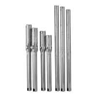
Impeller adjusting screws
1 Set screw
2 Fastening screw
3 Impeller clearance
The following method is suitable for pumps in vertical
position. Proceed as follows:
1. Loosen the fastening- and set screws so the
impeller is sitting on the suction cover / stationary
wear ring. When the impeller is in this position, the
impeller clearance is zero.
2. Tighten the three set screws down by hand until
they touch the top surface of the volute.
3. The impeller clearance is created by turning the
set screws to a specified angle. Closed S-tube
®
and open S-tube
®
impellers, as well as the
different head classes, have different impeller
clearances. See the table above to determine the
correct impeller clearance and turning angle.
4. Once the correct angle is identified, turn the set
screw clockwise by the specified angle. Use a
turning gauge to ensure the set screw is tightened
to the correct amount.
5. Tighten the fastening screws in two steps,
according to the sequence below:
• Tighten the screws one by one, from 1 to 6.
Required torque: 40 ± 4 Nm.
• Repeat the previous sequence to the final
torque of 70 ± 4 Nm
TM077792
Tightening sequence
8.3 Maintaining the explosion-proof SE, SL
pumps
Overhauled and repaired explosion-proof pumps are
marked with a repair plate providing the following
information:
• repair symbol R
• name or registered trademark of the repairing
workshop
• workshop reference number relating to the repair
• date of overhaul or repair.
In the event of subsequent repairs, the existing plate
must be replaced by a new updated one and earlier
markings must be recorded.
The repairing workshop must keep records of
performed overhauls and repairs with records of all
previous overhauls, repairs and possible
modifications. Copies of the detailed records of the
repairing workshop must be filed by the owner or
operator with the original type certificate of the
explosion-proof motor.
8.3.1
Power cable
Use manufacturer-approved and compatible cables
thatare suitable for the cable entry.
8.3.2
Cable entry
Use only Ex cable entry parts corresponding to the
cable diameter. The correct cable dimension marking
is stamped on the inlet or the cable entry.
27
English (GB)