8.3 Cleaning and inspecting the pump
Clean the pump on site at regular intervals in the following way:
• Lift the pump out of the tank.
• Hose down the pump externally by using a high-pressure
cleaner at a maximum of 100 bar.
• Remove caked dirt from the motor to ensure appropriate heat
conductivity. A mild detergent, which is approved for disposal
into the sewage system, may be used.
• If necessary, scrub the pump with a soft brush.
Visual inspection of the pump must include the following:
• Search for cracks or other external damage.
• Check the lifting bracket and lifting chain for wear and corrosion.
• Inspect the power cable for cracks, lacerations, kinks, or other
damage in the sheath.
• Inspect the visible parts of the cable entry for cracks.
• Check that the cable is firmly connected to the top cover.
• Check all visible screws for self-loosening and tighten them, if
necessary.
The pump is fitted with a vent valve at the bottom of the cooling
jacket. The valve may be removed and cleaned, if necessary. Clean
the vent hole before refitting the valve after cleaning.
8.4 Checking the sensors
Sensor check measurements must be made by Grundfos
or persons authorised by Grundfos.
Make the measurements from the free end of the cable (10 m) while
the other end of the cable is connected to the pump. In case the
pump cable is longer than 10 m, contact Grundfos for correct
values.
Sensors can be checked by using the Grundfos Test Box or a
multimeter.
8.4.1
Checking with Test Box
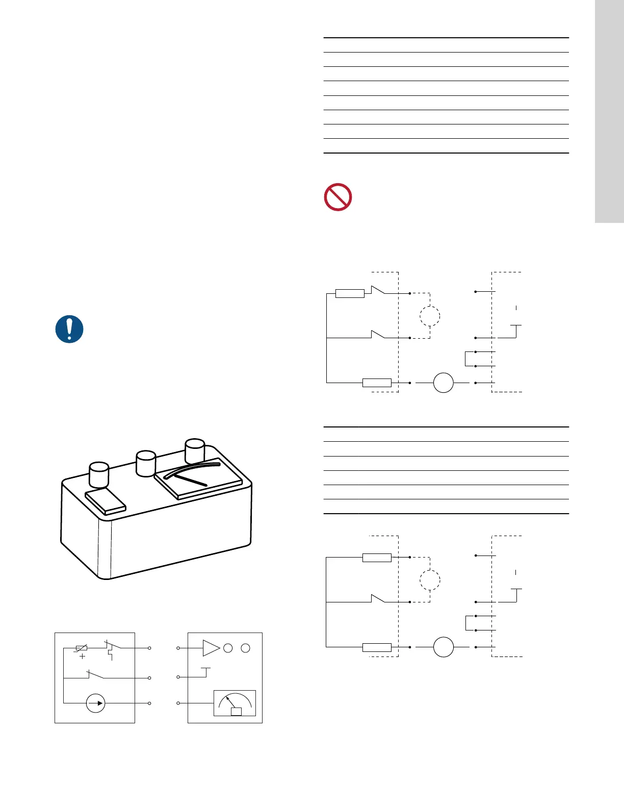
TM048000
Text box
1. Connect the text box and sensors according the wiring diagram.
T
M
T1/P1 T1
T2/P2
T2
T5/P5
T5
mA
TM048022_2710
Wiring diagram for test box and sensors
2. Check the following table:
Fault
LED Output [mA]
None Green 4-20
Moisture Red 0
No pump Red 0
Temperature Red 4-20
WIO Green 0
WIO - air (WIA) Green 3.5
WIO - water Green 22
8.4.2 Checking with a Multimeter
Do not use a megaohmmeter for checking the sensor as it
will damage the control circuit.
If the measured value is Ω, disconnect the conductors from IO 113.
If the measured value is mA, disconnect conductor 6 (9) from P5
and connect the standard instrument to 6 (9) and P5.
Pt1000
T
M
WIO
P
4 (7)
5 (8)
6 (9)
mA
IO 113
10-c
P2
P3
P4
P5
+ 15 V
Ʊ
TM047039
Pump with Pt1000 sensor
Pos. Description
P Pump
I Internal +15 V
10-c 10-core cable
T Thermal switch
M Moisture switch
P
PTC
M
WIO
4 (7)
5 (8)
6 (9)
mA
IO 113
P1
P2
P3
P4
P5
+15 V
Ʊ
10-c
TM047040
Pump with PTC sensor
23
English (US)