11.3 Fitting the sleeve
1. Place the motor in horizontal position on wooden bars.
2. Fit and lubricate the O-rings (37a).
3. Fit the oil plug (193) and the washers (194).
4. Lubricate the lower inner part of the sleeve (150) with O-ring
grease.
5. Lower the sleeve (150) down on the stator housing (55).
6. Fit the sleeve (150) and knock with a hammer and a wooden
block if needed.
Related information
8.1 Servicing Grundfos pumps with explosion-proof motors
11.4 Fitting the shaft
1. Place the motor housing horizontally with a crane.
2. Fit the corrugated spring (158) into the stator housing (55). It
may need to be kept in position with a small amount of grease.
3. Lubricate the outside of the upper bearing (154) with O-ring
grease.
4. Fit and lubricate the O-ring (108) to the upper bearing cover
(60).
5. Fit the cover on the shaft (172).
6. Insert the rotor and shaft (172) into the stator housing (55) so
that the upper bearing (154) goes first. Take care not to damage
or pinch the WIO sensor (521), if any.
7. Align the groove in the bearing housing (60) to the cable entry of
the intermediate flange (155).
8. Fit the upper bearing (154) to the shaft (172).
Bearings are factory-greased.
Related information
8.1 Servicing Grundfos pumps with explosion-proof motors
11.5 Fitting the lower bearing
1. Fit the lower bearing (153) on the upper bearing cover (60). Fill
the bearing with grease.
2. Fit the corrugated spring (157).
3. Fit and lubricate the O-ring (109) to the lower bearing cover
(59).
4. Fit the lower bearing cover (59) to the shaft (172).
5. Fit the screws (182) and tighten them diagonally.
Related information
8.1 Servicing Grundfos pumps with explosion-proof motors
11.6
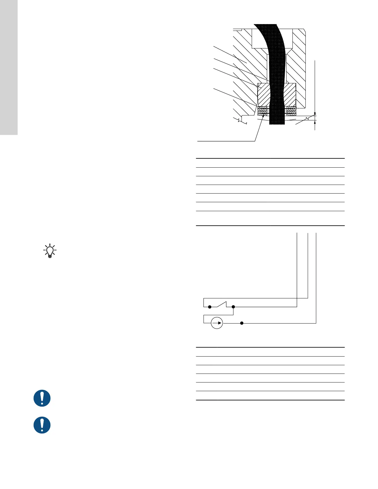
Fitting the WIO sensor
Fit the sensor next to one of the shaft seal openings. The
sensor must be tilted into the motor’s direction of rotation
to ensure that oil is led into the sensor. Make sure that the
sensor is submerged in the oil.
Upon removal of disc springs and the rubber bush, they
must always be replaced.
Position of disc springs and the rubber bush
Pos. Description
1 Sensor cable
2 Rubber bush
3 Disc spring
4 Disc spring stack
155 Intermediate flange
X
Minimum compression is 0.05
" (1.4 mm)
Wiring diagram for WIO sensor
Pos. Description
M Moisture switch
Br Brown
W White
Bl Blue
Bla Black
28
English (US)
 Loading...