In case of abnormal noise or vibration, stop the pump
immediately. Do not restart the pump until the cause of the
fault is identified and eliminated.
CAUTION
Sharp element
Minor or moderate personal injury
‐ Do not touch the sharp edges of the impeller without
wearing protective gloves.
After a short period of storage, vent the pump to let any
explosive gasses escape.
12.1.1 SE1 pumps
1. Remove the fuses and check that the impeller can rotate freely.
Turn the impeller by hand.
2. Check the condition of the oil in the oil chamber.
3. Check that the system, bolts, gaskets, pipes, and valves are in
correct condition.
4. Check the direction of rotation.
5. Mount the pump in the system.
6. Switch on the power supply.
7. Check whether the monitoring units, if used, are operating
satisfactorily.
8. For pumps with sensor, switch on IO 113 and check that there
are no alarms or warnings.
9. Check the setting of the air bells, float switches or electrodes.
10. Open the isolating valves, if fitted.
11. Check that the liquid level is above the upper edge of the clamp.
If the level is below the clamp, add liquid to the tank until the
minimum level is obtained.
12. Remove trapped air from the pump housing by tilting the pump
by the lifting chain.
13. Start the pump and let it run briefly. Check if the liquid level is
falling. A correctly vented pump quickly lowers the liquid level.
After one week of operation or after replacement of the shaft seal,
check the condition of the oil in the chamber. For pumps without
sensor, this can be done by taking a sample of the oil.
12.1.2
SEV pumps
1. Remove the pump from the system.
2. Check that the impeller can rotate freely. Turn the impeller by
hand.
3. Check the condition of the oil in the oil chamber.
4. Check whether the monitoring units, if used, are operating
satisfactorily.
5. Check the setting of the air bells, float switches, or electrodes.
6. Check the direction of rotation.
7. Submerged pumps:
• Start the pump above the water level and lower it into the
tank to avoid air being trapped in the pump housing.
8.
Dry-installed pumps with positive inlet pressure (the pump
is installed in a pump room next to the tank):
• Open the isolating valve on the inlet side.
• Loosen the vent screw until water comes out of the vent hole,
then tighten the vent screw again.
• Open the isolating valve on the outlet side and start the
pump.
Check that there is positive inlet pressure before
starting up the pump.
9. Dry-installed pumps with inlet pipe and foot valve:
• Open the isolating valve on the outlet side to let the water
above the valve run backwards to prime the inlet pipe.
• Loosen the vent screw until water comes out of the vent hole,
then tighten the vent screw again.
• Start the pump.
10. Dry-installed pumps with inlet pipe and foot valve, with or
without short outlet pipe (use a vacuum system):
• Keep the isolating valve on the outlet side closed.
• Start the vacuum system until liquid is sucked in and the
pump is vented.
• Open the isolating valve on the outlet side and start the
pump.
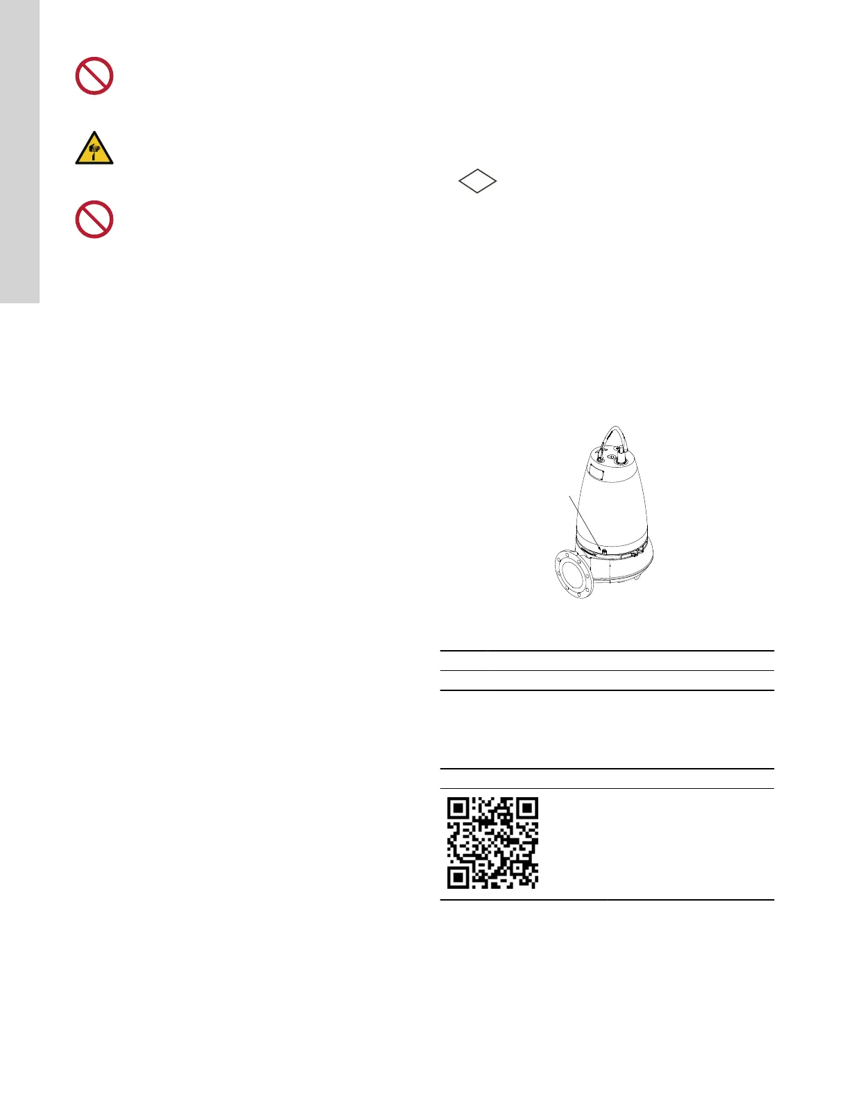
TM044139
Position of the air vent screw
Pos. Description
1 Air vent screw
13. Fault finding
For further information, see the installation and operating
instructions for SE1, SEV 1.5 - 15 hp.
Installation and Operating Instructions
http://net.grundfos.com/qr/i/
93010806
32
English (US)
 Loading...