English (GB)
22
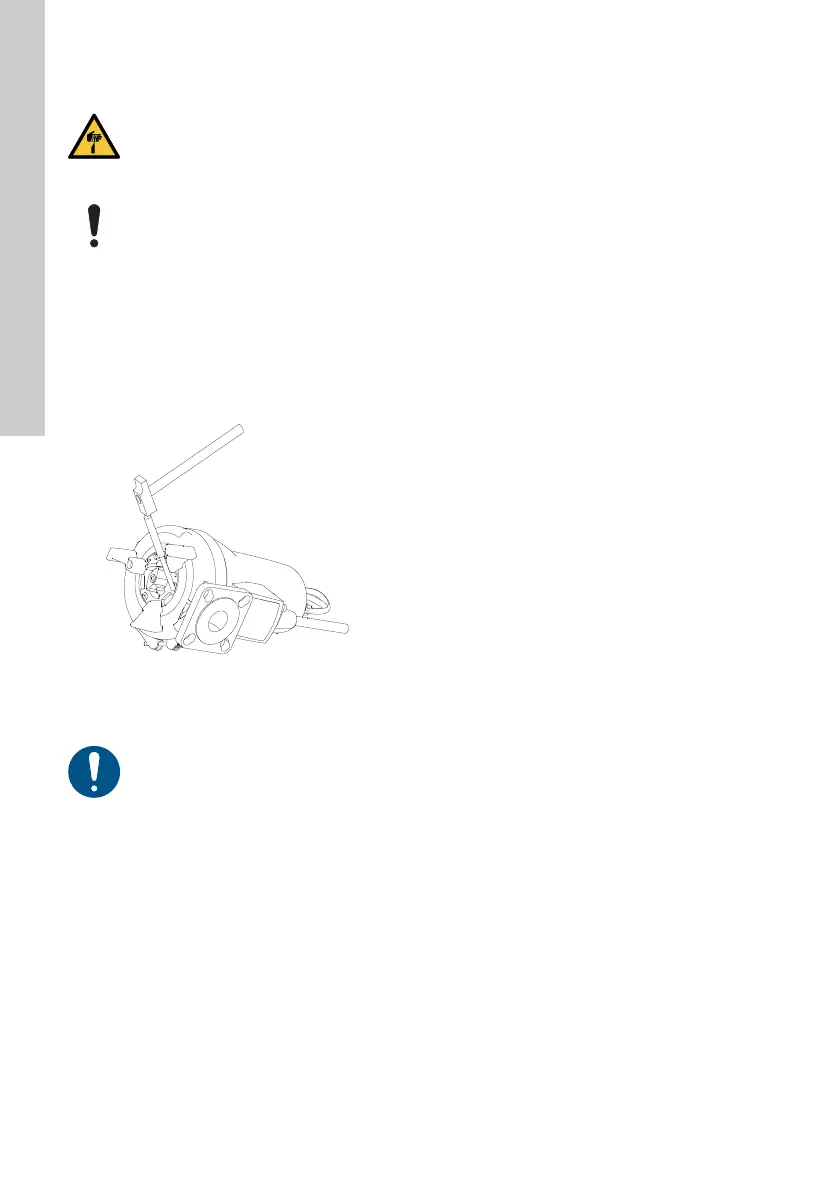
8.6 Replacing the grinder system
For position numbers in brackets, see fig, D in
Appendix.
Proceed as follows:
Dismantling
1. Loosen the screw (188a) in one of the pump feet.
2. Loosen the grinder ring (44), and open the
bayonet socket by knocking or turning the grinder
ring 15 to 20 ° clockwise. See fig. 13.
Fig. 13 Removing the grinder ring
3. Gently prise the grinder ring (44) out of the pump
housing with a screwdriver.
4. Insert a punch into the hole in the pump housing
to hold the impeller.
5. Remove the screw (188a) in the shaft end and
the locking ring (66).
6. Remove the grinder head (45).
Assembly
1. When fitting the grinder head (45), the
projections on the back of the grinder head must
engage with the holes in the impeller (49).
2. Tighten the screw (188a) for the grinder head to
20 Nm. Do not forget the lock washer.
3. Fit the grinder ring (44).
4. Turn the grinder ring (44) 15 to 20 ° counter-
clockwise until it is tightened.
5. Check that the grinder ring does not touch the
grinder head.
6. Tighten the screw (188a) to 16 Nm.
8.7 Cleaning the pump housing
For position numbers in brackets, see fig. D in
Appendix.
Proceed as follows:
Dismantling
1. Stand the pump upright.
2. Loosen and remove the clamp (92) joining the
pump housing and the motor.
3. Lift the motor out of the pump housing (50). As
the impeller and grinder head are fastened to the
shaft end, the impeller and the grinder head will
be removed together with the motor.
4. Clean the pump housing and the impeller.
Assembly
1. Place the motor with the impeller and the grinder
head in the pump housing.
2. Fit and tighten the clamp (92).
See also section 8.8 Checking or replacing the shaft
seal.
CAUTION
Sharp element
Minor or moderate personal injury
- Beware of the sharp edges on the
impeller, grinder head and grinder ring.
During service the painted surface may be
damaged. Remember to restore the
painted surface by applying new paint.
TM06 5746 0116
Make sure that the grinder ring does not
get stuck against the grinder head.
 Loading...