English (GB)
8
4.3 Ensuring motor cooling
Fig. 1 Minimum distance (D) from the motor to a wall or other
fixed objects
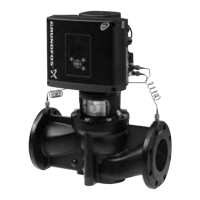
4.4 Outdoor installation
When installed outdoors, the motor must be provided with a
suitable cover to avoid condensation on the electronic
components. See fig. 2.
The cover must be sufficiently large to ensure that the motor is
not exposed to direct sunlight, rain or snow. Grundfos does not
supply covers. We therefore recommend that you have a cover
built for the specific application. In areas with high air humidity,
we recommend that you enable the built-in standstill heating
function.
Fig. 2 Examples of covers (not supplied by Grundfos)
4.5 Drain holes
When the motor is installed in moist surroundings or areas with
high air humidity, the bottom drain hole should be open.
The enclosure class of the motor will then be lower. The open
drain hole helps prevent condensation in the motor as it will make
the motor self-venting and allow water and humid air to escape.
The motor has a plugged drain hole on the drive side. The flange
can be turned 90 ° to both sides or 180 °.
Fig. 3 Drain holes
5. Electrical installation
Carry out the electrical connection according to local regulations.
Check that the supply voltage and frequency correspond to the
values stated on the nameplate.
5.1 Protection against electric shock, indirect contact
Protective-earth conductors must always have a yellow/green
(PE) or yellow/green/blue (PEN) colour marking.
5.1.1 Protection against mains voltage transients
The motor is protected against mains voltage transients in
accordance with EN 61800-3.
5.1.2 Motor protection
The motor requires no external motor protection. The motor
incorporates thermal protection against slow overloading and
blocking.
In order to ensure sufficient cooling of the motor,
the distance (D) between the end of the fan cover
and a wall or other fixed objects must always be
at least 50 mm, irrespective of motor size.
See fig. 1.
TM05 5236 3512
When fitting a cover to the motor, observe the
guideline in section 4.3 Ensuring motor cooling.
TM05 7919 1613TM02 9037 1604
Warning
Before making any connections in the terminal
box, make sure that the power supply has been
switched off for at least 5 minutes. Make sure that
the power supply cannot be accidentally
switched on.
The motor must be connected to an external
all-pole mains switch according to local
regulations.
The motor must be earthed and protected against
indirect contact in accordance with local
regulations.
If the power supply cable is damaged, it must be
replaced by the manufacturer, the manufacturer’s
service partner or a similarly qualified person.
The user or the installer is responsible for the
installation of correct earthing and protection
according to local regulations. All operations
must be carried out by a qualified electrician.
Warning
The motor must be earthed and protected against
indirect contact in accordance with local
regulations.

 Loading...