F
E
100
90
80
70
60
50
40
30
20
10
25 50 100 150
200
250
[W]
[%]
A
B
C
D
TM050006
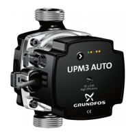
PWM feedback signal, UPM3 power consumption
100
90
80
70
60
50
40
30
20
10
25
50
100
150
200 250
A
B
C
D
[W]
[%]
G
H
TM050021
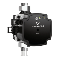
PWM feedback signal, UPM3L power consumption
Pos. Description
X-axis Output power consumption [W]
Y-axis PWM output signal in percentage [%]
A Standby (stop)
B Alarm stop: fault, blocked pump
C Alarm stop: electrical fault
D Warning
E Slope: 1 % / watt PWM signal
F Saturation at 70 W
G Slope: 2 % / watt PWM signal
H Saturation at 140 W
PWM out-
put signal
[%]
QT
[s]
Pump info
DT
[s]
Priority
95 0
Standby (stop) by PWM sig-
nal
0 1
90 30 Alarm, stop, blocked error 12 2
85 0-30 Alarm, stop, electrical error 1-12 3
75 0 Warning 0 5
0-70 0-70 W (slope 1 W/% PWM) 6
Output frequency: 75 Hz ± 5 %
QT = qualification time, DT = disqualification time
8.2.5
Control signal data levels
Maximum rating Symbol Value
PWM frequency input with high-
speed optocoupler
f
100-4000 Hz
*
Rated input voltage - high level
U
iH
4-24 V
Rated input voltage - low level
U
iL
< 1 V
High-level input current
I
iH
< 10 mA
Input duty cycle PWM 0-100 %
PWM frequency output, open collec-
tor
f 75 Hz ± 5 %
Accuracy of output signal regarding
power consumption
-
± 2 % (of PWM
signal)
Output duty cycle PWM 0-100 %
Collector emitter breakdown voltage
on output transistor
U
c
< 70 V
Collector current on output transistor
I
c
< 50 mA
Maximum power dissipation on output
resistor
P
R
125 mW
Zener diode working voltage
U
z
36 V
Maximum power dissipation in Zener
diode
P
z
300 mW
*
Only for standard profiles.
17
English (GB)