8.2 Control signals
8.2.1 Digital low-voltage PWM signal
WARNING
Explosive environment
Death or serious personal injury
‐ Do not exceed the specified maximum voltage on the
PWM output or the output circuit may overheat.
The square-wave PWM signal is designed for a 100 to 1500 Hz
frequency range. The PWM signal is used to select the speed
(speed command) and as feedback signal. The PWM frequency on
the feedback signal is fixed at 75 Hz in the pump.
Duty cycle
d % = 100 x t/T
Example Rating
T = 2 ms (500 Hz)
U
IH
= 4-24 V
t = 0.6 ms
U
IL
≤ 1 V
d % = 100 x 0.6 / 2 = 30 %
4.5 mA ≤ Ih ≤ 10 mA (depending on
U
IH
)
Example
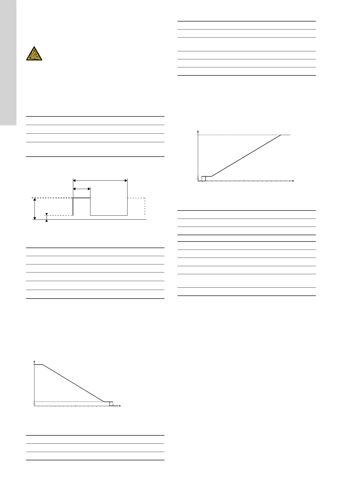
TM049911
PWM signal
Abbreviation Description
T Period of time [sec.]
d Duty cycle [t/T]
U
IH
High-level input voltage
U
IL
Low-level input voltage
I
IH
High-level input current
8.2.2 PWM input signal profile A (heating)
At high PWM signal percentages (duty cycles), a hysteresis
prevents the pump from starting and stopping if the input signal
fluctuates around the shifting point. At low PWM signal
percentages, the pump speed is high for safety reasons. In case a
cable breaks in a gas boiler system, the pumps will continue to run
at maximum speed to transfer heat from the primary heat
exchanger. This is also suitable for heat pumps to ensure that the
pumps transfer heat even if a cable breaks.
Max.
10
20
30 40
50 60 70
80
90
100
X
Y
TM049985
PWM input profile A (heating)
Axis Value
X PWM input signal [%]
Y Speed
PWM input signal [%] Pump status
≤ 10 Maximum speed
> 10 / ≤ 84
Variable speed from minimum to maxi-
mum speed
> 84 / ≤ 91 Minimum speed
> 91/95 Hysteresis area: on/off
> 95 / ≤ 100 Standby mode: off
8.2.3 PWM input signal profile C (solar)
At low PWM signal percentages (duty cycles), a hysteresis prevents
the pump from starting and stopping if the input signal fluctuates
around the shifting point. Without PWM signal percentages, the
pump stops for safety reasons. If a signal is missing, for example if
a cable breaks, the pump stops to avoid overheating of the solar
thermal system.
Max.
10 20
30
40 50
60
70
80
90 100
TM051575
PWM input profile C (solar)
Axis Value
X PWM input signal [%]
Y Speed
PWM input signal [%] Pump status
≤ 5 Standby mode: off
> 5 / ≤ 8 Hysteresis area: on/off
> 8 / ≤ 15 Minimum speed
> 15 / ≤ 90
Variable speed from minimum to maxi-
mum speed
> 90 / ≤ 100 Maximum speed
8.2.4 PWM feedback signal (standard)
The PWM feedback signal offers the same pump information as in
bus systems:
• current power consumption (accuracy ± 2 % of PWM signal)
• warning
• alarm
• operating status.
Alarms
Alarm output signals are available because some PWM output
signals are dedicated to alarm information. If a supply voltage is
measured below the specified supply voltage range, the output
signal is set to 75 %. If the rotor is locked due to deposits in the
hydraulics, the output signal is set to 90 % as this alarm has a
higher priority.
16
English (GB)