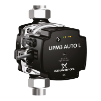
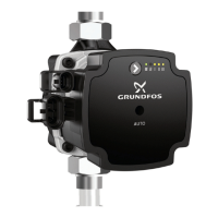
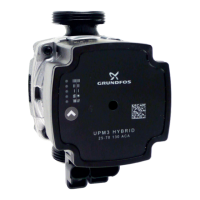
4. Mechanical installation
Mechanical installation must be carried out by trained per-
sons in accordance with local regulations.
The pump must always be installed with horizontal motor
shaft within ± 5 °.
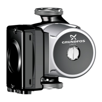
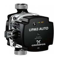
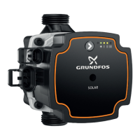
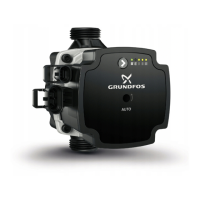
Arrows on the pump housing indicate the liquid flow direc-
tion through the pump. The pump is designed to be instal-
led with horizontal shaft pumping upwards, downwards or
horizontally.
• The pump must be installed in the system in such a way that no
major amount of air flowing through or gathering in the pump
housing affects the pump when it is out of operation.
• If an additional non-return valve is installed in the flow pipe,
there is a high risk of dry running as the air cannot pass the
valve.
• It must be possible to vent the system at the highest part of
each system segment.
• Permanent venting is recommended.
1. Check the arrows on the pump housing for flow direction
through the pump. The flow direction can be horizontal or
vertical, depending on the control box position.
TM078758TM080999
2. Close the isolating valves and make sure that the system is not
pressurised during the installation of the pump.
TM078759
3. Mount the pump with gaskets in the pipes.
TM078760
4. Tighten the union nuts (maximum 30 Nm).
TM078761
In heating systems, do not insulate the control box or cov-
er the operating panel.
7
English (GB)
 Loading...

