7.4.1 UPM3 HYBRID
This pump is either externally controlled with PWM signal with
profile A or C or internally with three control modes with
AUTO
ADAPT
(AA).
Control mode
LED1
green
LED2
green
LED3
yellow
LED4
yellow
LED5
yellow
PP AA ●
CP AA ●
PP1 ● ●
PP2 ● ● ●
PP3 ● ● ● ●
CP1 ● ●
CP2 ● ● ●
CP3 ● ● ● ●
CC1 ●
CC2 ● ●
CC3 ● ● ●
PWM C signal off
●
1
● ● ●
PWMC signal on
●
2
● ● ●
PWM A
curve 1 signal off
●
1
●
PWM A curve 1 signal on
●
2
●
PWM A curve 2 signal off
●
1
● ●
PWM A curve 2 signal on
●
2
● ●
PWM A curve 3 signal off
●
1
● ● ●
PWM A curve 3 signal on
●
2
● ● ●
1
1 flash per second.
2
12 flashes per second.
7.4.2
UPM3 FLEX AS and UPM3 DHW
This pump is either externally controlled with a PWM A profile signal
control or speed selection.
The maximum curve of the pump operating range can be defined.
• With PWM signal, the pump runs at the corresponding speed.
• Without PWM signal, the pump runs at maximum speed.
PWM A profile
LED1
green
LED2
green
LED3
yellow
LED4
yellow
LED5
yellow
PWM A curve 1 signal off
●
1
●
PWM A
curve 1 signal on
●
2
●
PWM A
curve 2 signal off
●
1
● ●
PWM A
curve 2 signal on
●
2
● ●
PWM A
curve 3 signal off
●
1
● ● ●
PWM A
curve 3 signal on
●
2
● ● ●
1
1 flash per second.
2
12 flashes per second.
7.4.3
UPM3 SOLAR
This pump is either externally controlled with PWM signal control
with profile C or internally on constant curve mode.
Control mode
LED1
green
LED2
green
LED3
yellow
LED4
yellow
LED5
yellow
CC1 ●
CC2 ● ●
CC3 ● ● ●
PWM C signal off
●
1
● ● ●
PWM C signal on
●
2
● ● ●
1
1 flash per second.
2
12 flashes per second.
7.4.4 UPM3 AUTO
This pump is internally controlled with three control modes with
AUTO
ADAPT
(AA).
Control mode
LED1
green
LED2
green
LED3
yellow
LED4
yellow
LED5
yellow
PP AA ●
CP AA ●
PP1 ● ●
PP2 ● ● ●
PP3 ● ● ● ●
CP1 ● ●
CP2 ● ● ●
CP3 ● ● ● ●
CC1 ●
CC2 ● ●
CC3 ● ● ●
7.4.5 UPMO
This pump is internally controlled with control mode CC or
externally with PWM signal control with profile A.
The pump automatically enables the PWM input-signal control
mode by SignalDetect when the signal cable is plugged in.
Control mode
LED1
green
LED2
green
LED3
yellow
LED4
yellow
LED5
yellow
CC1 ●
CC2 ● ●
CC3 ● ● ●
PWM A
●
1
● ● ●
1
12 flashes per second.
If the pump does not detect a PWM signal or if the signal equals 0,
the pump returns to its previous control mode.
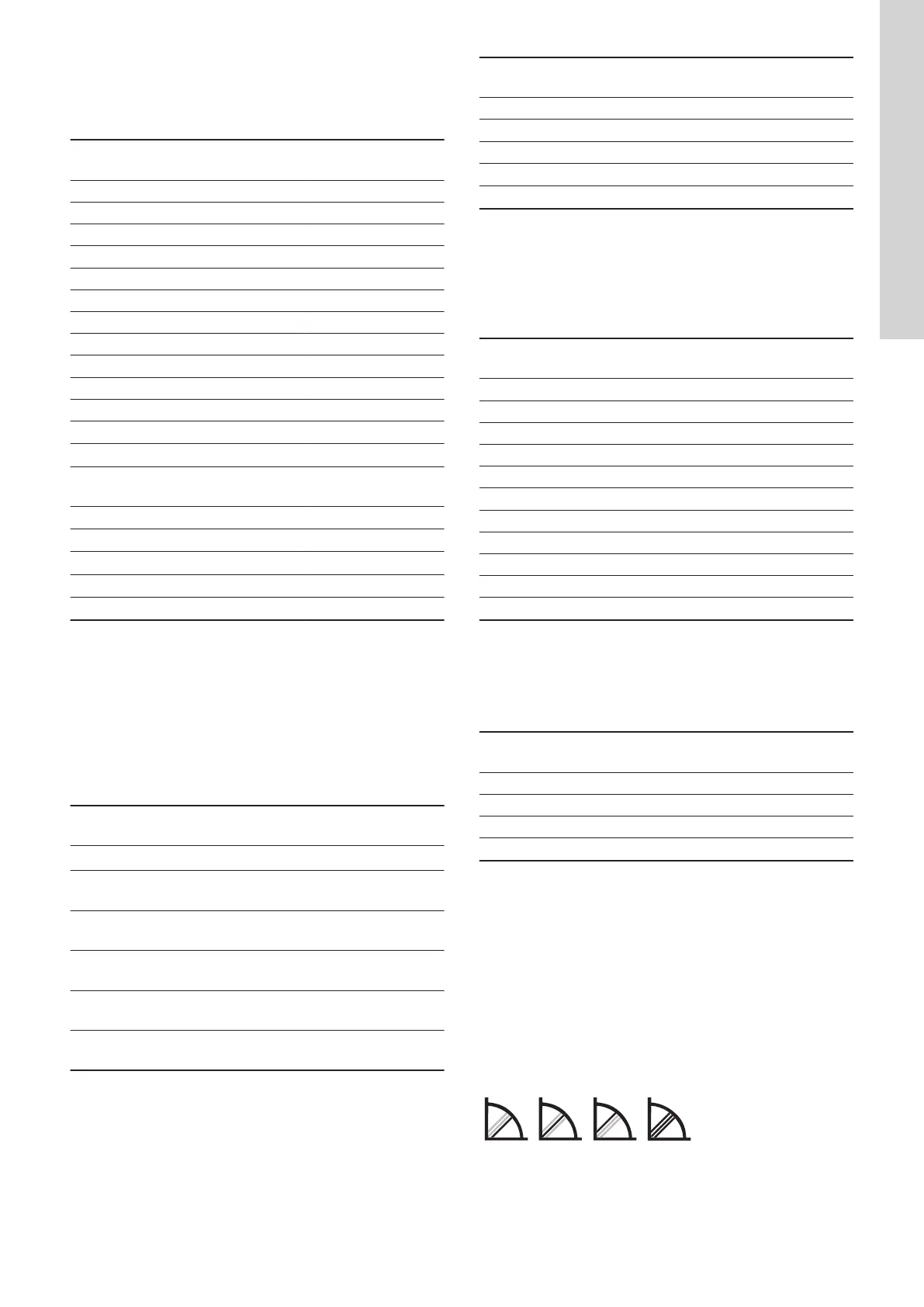
7.5 Control mode explanation
7.6
Proportional pressure
The head (pressure) is reduced at falling heat demand and
increased at rising heat demand.
The duty point of the pump moves up or down on the selected
proportional-pressure curve depending on the heat demand in the
system.
TM060704
• PP1: lowest proportional-pressure curve
• PP2: intermediate proportional-pressure curve
• PP3: highest proportional-pressure curve
• AUTO
ADAPT
: highest to lowest proportional pressure curve.
13
English (GB)