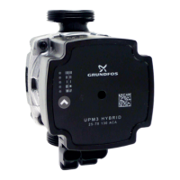
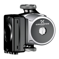
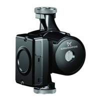
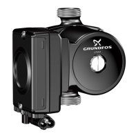
15. Performance curves and technical data
Curve conditions
The guidelines below apply to the performance curves:
• Test liquid: airless water.
• The curves apply to a density of 998.21 kg/m
3
and a
liquid temperature of +20 °C.
• All curves show average values and should not be
used as guarantee curves. If a specific minimum
performance is required, individual measurements
must be made.
• The curves apply to a kinematic viscosity of 1.004
mm
2
/s (1.004 cSt).
• The conversion between head H [m] and pressure p
[kPa] has been made for water with a density of 1000
kg/m
3
. For liquids with other densities, for example
hot water, the outlet pressure is proportional to the
density.
• Curves obtained according to EN 16297.
• Pump variants with PWM signal connection are
designed to be speed controlled by an external
system controller. Therefore, EEI and P
L,Avg
of the
different pump heads (pumps without pump
housings) are measured to be in compliance with the
Ecodesign requirements of regulation EC/622/2012
with a reference housing in accordance with EN
16297-3.
• It is not obligatory to show P
L,Avg
but it gives an
indication on the yearly expectable average power
consumption.
• The performance of PWM controlled pumps is
measured with A profile (heating) at eight PWM
values: 5 % (max.), 20 %, 31 %, 41 %, 52 %, 62 %,
73 %, 88 % (min.).
• C profile curves are measured mirrored with 95 %
(max.), 80 %, 69 %, 59 %, 48 %, 38 %, 27 %, 12 %
(min.)
• Maximum curves are limited by speed and power
• Variants with two different minimum curves are
available: minimum curve A (standard) at
approximately 0.1 m and minimum curve J (option) at
approximately 1 m.
• Other curves for different control signals or OEM
housings are available on request.
Measured pump head variants
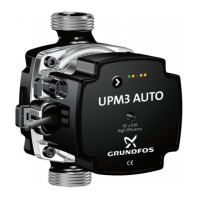
UPM3S
Product mark
P
1
max. nom. [W]
EEI Part 3
PWM
XX-40 GFNHB - ≤ 0.20
XX-50 GFNHB - ≤ 0.20
XX-60 GFNHB 42 ≤ 0.20
LIN XX-60 GFNHB 42 ≤ 0.20
FLEX AS XX-60 GFNHB 42 ≤ 0.20
AUTO XX-60 GFNHB 42 ≤ 0.20
HYBRID XX-60 GFNHB 42 ≤ 0.20
UPM3 Product mark
P
1
max. nom. [W]
EEI Part 3
PWM
XX-50 GFNKB 33 ≤ 0.20
XX-60 GFNKB 39 ≤ 0.20
XX-70 GFNKB 52 ≤ 0.20
XX-75 GFNKB 60 ≤ 0.20
LIN XX-75 GFNKB 60 ≤ 0.20
FLEX AS
XX-50 GFNKB 33 ≤ 0.20
XX-70 GFNKB 52 ≤ 0.20
XX-75 GFNKB 60 ≤ 0.20
AUTO
XX-50 GFNKB 33 ≤ 0.20
XX-70 GFNKB 52 ≤ 0.20
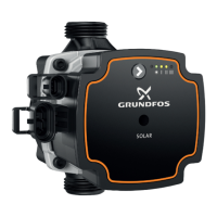
SOLAR
XX-75 GFNKB 45 ≤ 0.20
XX-105 GFNKB 52 ≤ 0.20
XX-145 GFNKB 60 ≤ 0.20
DHW
XX-20 GFNKB 11 ≤ 0.20
XX-50 GFNKB 33 ≤ 0.20
XX-70 GFNKB 52 ≤ 0.20
HYBRID
XX-50 GFNKB 33 ≤ 0.20
XX-70 GFNKB 52 ≤ 0.20
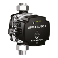
UPM3L Product mark
P
1
max. nom. [W]
EEI Part 3
PWM XX-75 GFNKC 75 ≤ 0.20
LIN XX-75 GFNKC 75 ≤ 0.20
FLEX AS XX-75 GFNKC 75 ≤ 0.20
AUTO XX-70 GFNKC 75 ≤ 0.20
HYBRID XX-70 GFNKC 75 ≤ 0.20
UPMO Product mark
P
1
max. nom. [W]
EEI Part 3
UPMO XX-50 GFNKB 39 ≤ 0.23
UPMO XX-60 GFNKB 60 ≤ 0.23
UPMO XX-70 GFNKC 75 ≤ 0.23
UPM3
15
59
Performance curves and technical data
 Loading...

