7. External control mode and signals
Control principles
The UPM3 and UPM3 FLEX pumps are controlled via a
digital low-voltage pulse-width modulation (PWM) signal
which means that the speed of rotation depends on the
input signal.
UPM3 HYBRID pumps can be set to either internally or
externally controlled. The speed changes as a function of
the input profile. These communication signals are
standardised in the VDMA Einheitsblatt 24244 "Wet
runner circulating pumps - Specification of PWM control
signals".
Control signals
Digital low-voltage PWM signal
The square-wave PWM signal is designed for a 100 to
4,000 Hz frequency range. The PWM signal is used to
select the speed (speed command) and as feedback
signal. The PWM frequency on the feedback signal is
fixed at 75 Hz in the pump.
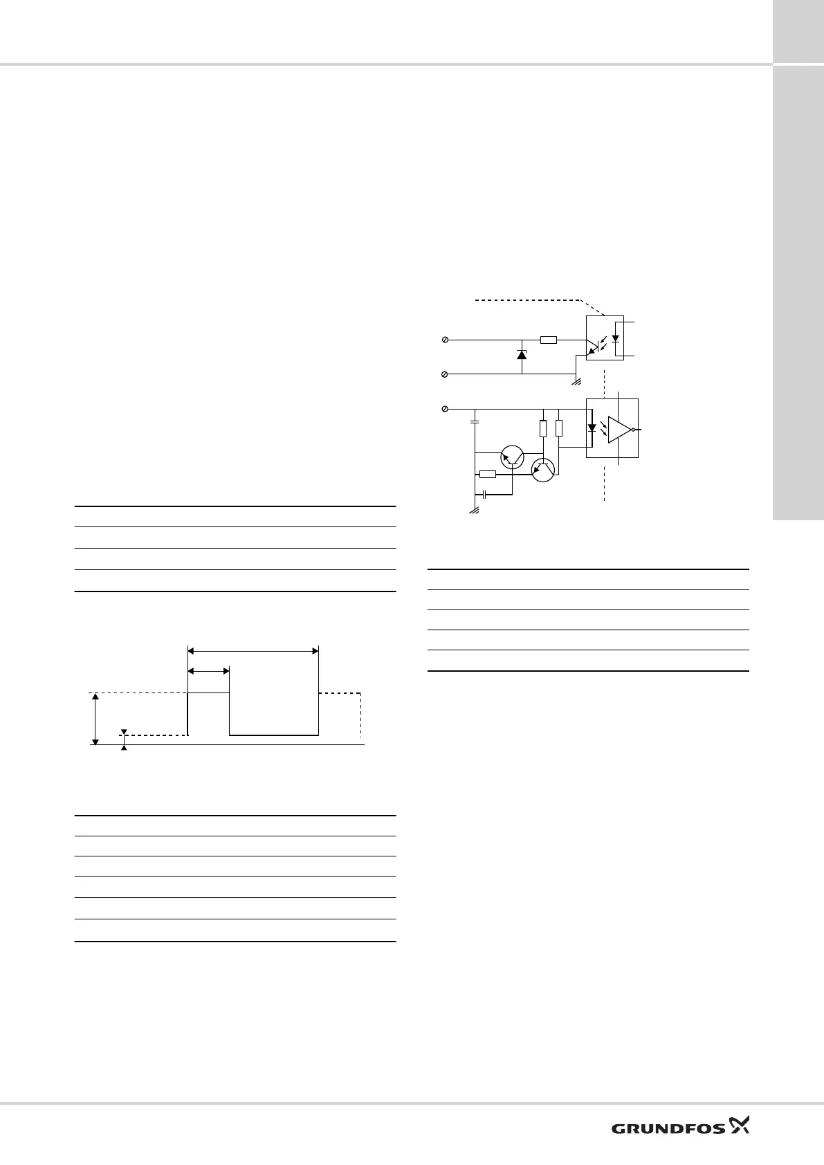
Duty cycle
d % = 100 x t/T
Example Rating
T = 2 ms (500 Hz)
U
IH
= 4-24 V
t = 0.6 ms
U
IL
≤ 1 V
d % = 100 x 0.6 / 2 = 30 %
I
IH
≤ 10 mA (depending on U
IH
)
Example
TM049911
PWM signal
Abbreviation Description
T Period of time [sec.]
d Duty cycle [t/T]
U
IH
High-level input voltage
U
IL
Low-level input voltage
I
IH
High-level input current
PWM interface
The PWM interface consists of an electronic part
connecting the external control signal to the pump. The
interface translates the external signal into a signal type
that the microprocessor can understand.
In addition, the interface ensures that the user cannot get
into contact with dangerous voltage if touching the signal
wires when power is connected to the pump.
470R
36V
100p
110R
BC847B
BC847B
TLP2704
TLP383
68k
2k7
+
-
1
2
3
4
TM060787
Schematic drawing, interface
Pos. Description
1 Galvanic isolation
2 PWM output
3 Signal reference (without connection to protective earth)
4 PWM input
Related information
UPM3
UPM3
7
17
External control mode and signals

 Loading...