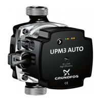
8. Control modes, operating panel and settings
UPM3
UPM3 is externally controlled via a PWM or LIN bus
signal.
Related information
PWM interface
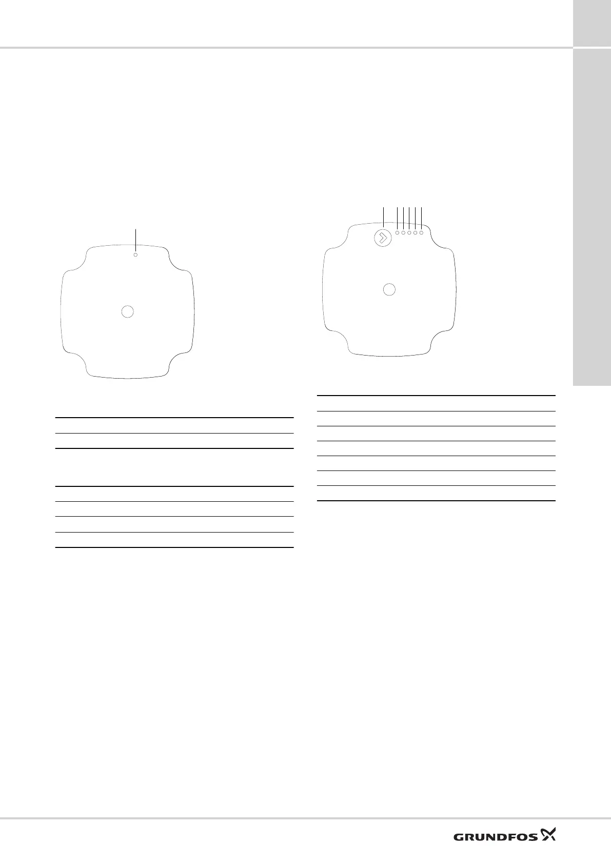
Operating panel
The operating panel is designed with one red/green LED.
TM075425
UPM3 operating panel
Pos. Description
A LED
The LED shows whether or not the pump is controlled
externally or if the pump experiences an error.
Green LED
Red LED
No external control ●
External control
●
1
Alarm ●
1
12 flashes per second.
Alarm status
If the pump detects an alarm, the LED switches from
green to red. This can mean one of the following:
• Low supply voltage
• Blocked rotor
• Electrical error.
The alarms for blocked rotor and electrical error can be
read out via the PWM return signal, while all three alarms
can be read out via the LIN bus signal.
For information about remedy, see 13. Service.
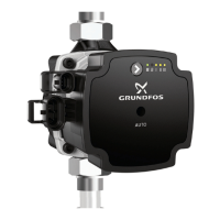
UPM3 HYBRID variants
UPM3 HYBRID variants can be controlled both externally
and internally.
Operating panel
The operating panel is designed with a single button, one
red/green LED and four yellow LEDs.
TM0605351
Operating panel with one button and five LEDs
Pos. Description
A Push button
B LED 1
C LED 2
D LED 3
E LED 4
F LED 5
The operating panel shows:
• control mode
• alarm status.
Alarm status
If the pump has detected one or more alarms, LED 1
switch from green to red and one of the other LEDs lights
yellow. See information about fault finding.
If multiple alarms are active at the same time, the LEDs
only show the error with the highest priority. The priority is
defined by the sequence of the table as shown in the fault
finding information.
When there is no active alarm anymore, the operating
panel switches back to the operation mode.
UPM3
8
21
Control modes, operating panel and settings

 Loading...