[%]
100
90
80
70
60
50
40
30
20
10
0.25
0.50
1.00
1.50
2.00 2.50
E
F
[Q]
A
B
C
D
TM071356
PWM feedback signal - flow estimation
Pos. Description
A Standby (stop)
B Alarm stop: fault, blocked pump
C Alarm stop: electrical fault
D Warning
E
Slope: 0.03 [m
3
/h]/% PWM
F
Saturation at 2.1 [m
3
/h]
Control signal data levels
Maximum rating
Symbol Value
PWM frequency input with high-speed
optocoupler
f 100-4000 Hz
Guaranteed standby power
consumption
< 1 W
Rated input voltage - high level
U
iH
4-24 V
Rated input voltage - low level
U
iL
< 1 V
High-level input current
I
iH
< 10 mA
Input duty cycle PWM 0-100 %
PWM frequency output, open collector f 75 Hz ± 5 %
Accuracy of output signal regarding
power consumption
- ± 2 % (of PWM signal)
Output duty cycle PWM 0-100 %
Collector emitter breakdown voltage
on output transistor
U
c
< 70 V
Collector current on output transistor
I
c
< 50 mA
Maximum power dissipation on output
resistor
P
R
125 mW
Zener diode working voltage
U
z
36 V
Maximum power dissipation in Zener
diode
P
z
300 mW
LIN bus
The LIN variant is ready for the Local Interconnect
Network (LIN) bus communication protocol that is
standardised in the "VDMA Einheitsblatt 24226". This data
bus has been developed as LIN in the automotive sector
and enables great interchange of data between the pump
and the HVAC application.
New unique features such as hydronic balancing of
heating systems via the Grundfos GO Balance app can be
set using LIN bus communication.
In order to provide you the best support, Grundfos has
divided the LIN bus data points into six specific modules:
• Grundfos LIN Basic
• Control module
• Performance module
• Limit Feedback module
• Diagnostics module
• GO Balance module.
.
Contact your local Grundfos HVAC OEM representative to
learn more about LIN bus.
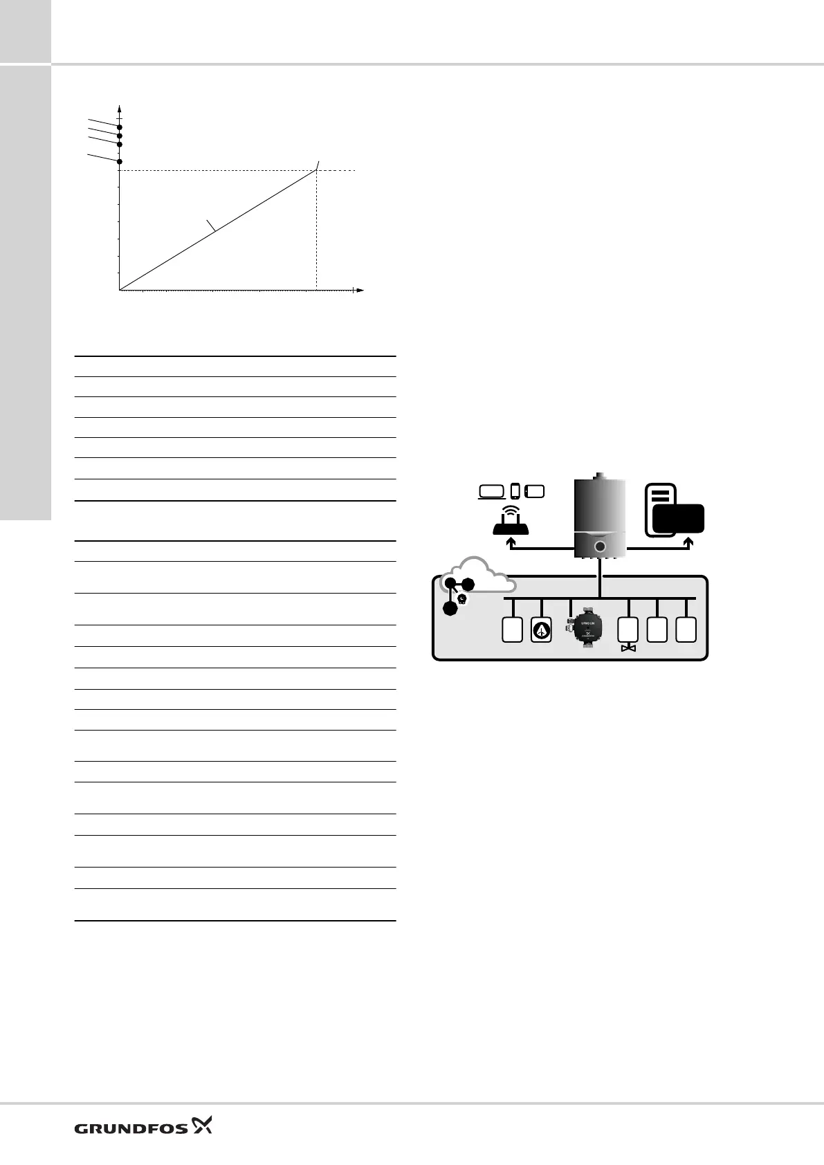
CONNECTIVITY
LIN BUS
M ϑ pV
•
BMS
BUILDING MANAGEMENT
SYSTEM
TM068459
LIN bus on fieldbus of heating control systems
UPM3
7
20
External control mode and signals
 Loading...