PWM feedback signal (standard)
The PWM feedback signal offers pump information like in
bus systems:
• current power consumption (accuracy ± 2 % of PWM
signal)
• warning
• alarm
• operating status.
Alarms
Alarm output signals are available because some PWM
output signals are dedicated to alarm information. If a
supply voltage is measured below the specified supply
voltage range, the output signal is set to 75 %. If the rotor
is locked due to deposits in the hydraulics, the output
signal is set to 90 % because this alarm has a higher
priority.
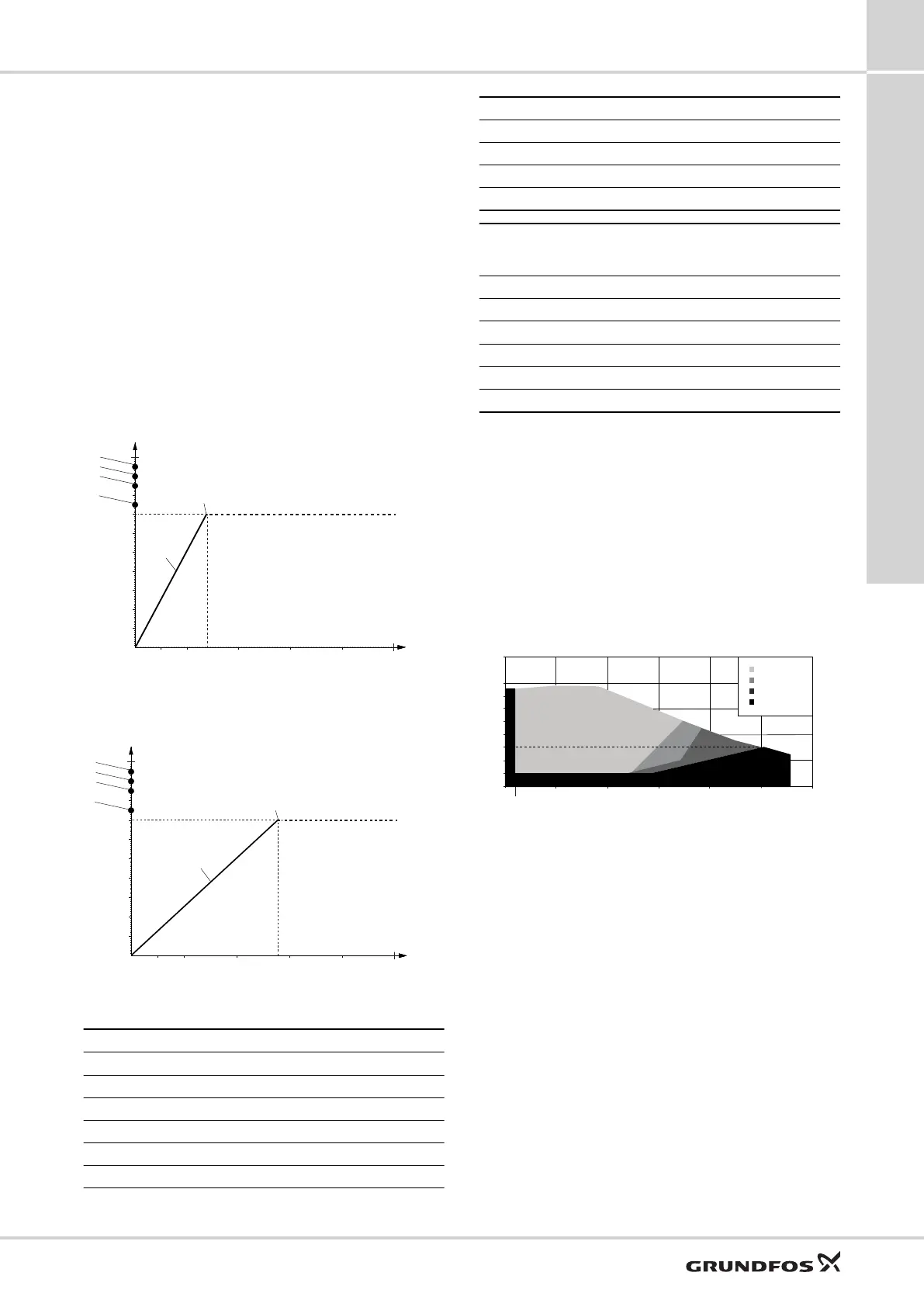
F
E
100
90
80
70
60
50
40
30
20
10
25 50 100 150
200
250
[W]
[%]
A
B
C
D
TM050006
PWM feedback signal, UPM3 power consumption
100
90
80
70
60
50
40
30
20
10
25
50
100
150
200 250
A
B
C
D
[W]
[%]
G
H
TM050021
PWM feedback signal, UPM3L power consumption
Pos. Description
X-axis Output power consumption [W]
Y-axis PWM output signal in percentage [%]
A Standby (stop)
B Alarm stop: Fault, blocked pump
C Alarm stop: Electrical fault
D Warning
Pos. Description
E Slope: 1 % / watt PWM signal
F Saturation at 70 W
G Slope: 2 % / watt PWM signal
H Saturation at 140 W
PWM
output signal
[%]
QT
[s]
Pump info
DT
[s]
Priority
95 0 Standby (stop) by PWM signal 0 1
90 30 Alarm, stop, blocked error 12 2
85 0-30 Alarm, stop, electrical error 1-12 3
75 0 Warning 0 5
0-70 0-70 W (slope 1 W/% PWM) 6
Output frequency: 75 Hz ± 5 %
QT = qualification time, DT = disqualification time
PWM feedback signal - flow estimation (on
request)
On request, there is an option where the PWM feedback
signal can also be used to indicate the flow of the pump
on defined pump housings (e.g. cast iron inline) above a
head of 1 m. The accuracy of the feedback signal is
depending on the media, media temperature and
operation point, but it gives an indication on the actual
flow (see figure below).
H [m]
±0.15 m³/h
±0.25 m³/h
±0.35 m³/h
Not def.
Q[m3/h]
0
0 0.5
1.0
1.5 2.0 2.5
0.15
1
2
3
4
6
8
10
TM076598
Accuracy of PWM feedback signal - flow estimation with
water at 40 °C
Example: In this case the PWM output range between
0-70 % shows the flow between 0 and 2.1 m
3
/h with a
slope of 0.03 m
3
/h / % PWM (see figure below).
UPM3
7
19
External control mode and signals
 Loading...