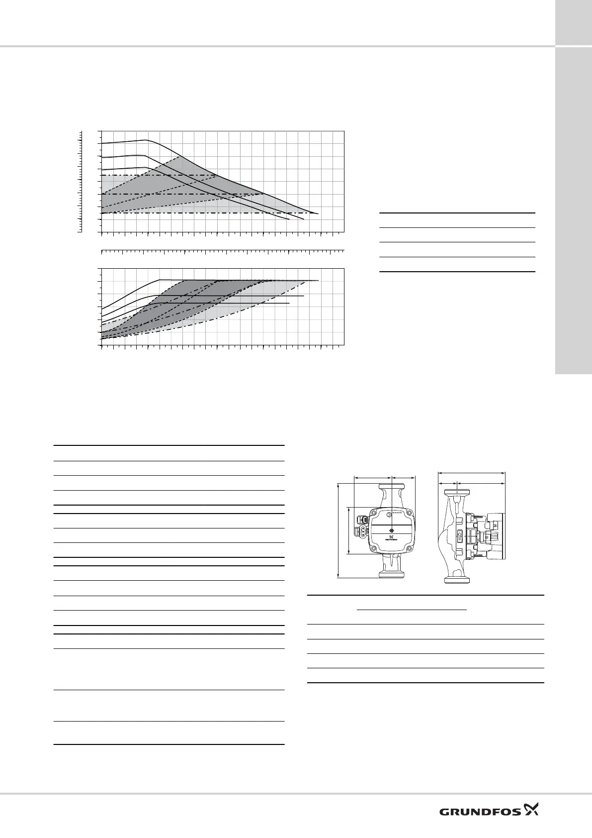
UPM3(K) HYBRID XX-70 130/180 (N)
(GFNKB)
0.0 0.2 0.4 0.6 0.8 1.0 1.2 1.4 1.6 1.8 2.0 2.2 2.4 2.6 2.8 3.0 3.2 3.4 3.6
Q [m³/h]
0
1
2
3
4
5
6
7
[m]
H
0
10
20
30
40
50
60
[kPa]
p
0.0 0.1 0.2 0.3 0.4 0.5 0.6 0.7 0.8 0.9 1.0
Q [l/s]
0.0 0.2 0.4 0.6 0.8 1.0 1.2 1.4 1.6 1.8 2.0 2.2 2.4 2.6 2.8 3.0 3.2 3.4 3.6
Q [m³/h]
0
10
20
30
40
50
[W]
P1
TM061179
Line type Description
________ Constant curve
_ _ _ _ _ _ Proportional pressure
__ . __ . __ . __ Constant pressure
EEI ≤ 0.20 Part 3
P
L,avg
≤ 25 W
Setting
Max. head
nom
Max. P
1
nom
Curve 1 5 m 33 W
Curve 2 6 m 39 W
Curve 3 7 m 52 W
Pump settings
PWM A PWM C PP CP CC
3 1 3/AA 3/AA 3
Electrical data, 1 x 230 V, 50 Hz
Speed
P
1
[W] I
1/1
[A]
Min. 2 0.04
Max. 52 0.52
Technical data
System
pressure
Max. 1.0 MPa (10
bar)
Enclosure
class
IP44 (non-
condensing)
K: IPX4D
(condensing)
Minimum inlet
pressure
0.05 MPa (0.50
bar) at 95 °C liquid
temperature
Motor
protection
No external
protection
needed
Liquid
temperature
2-110 °C (TF110)
Approval
and marking
VDE, CE
Dimensions
TM063879
Pump type
Dimensions [mm]
Connections
[inch]
Weight
[kg]
L1 L3 B1 B2 H1 H2 H3
15-70 130 (N) 130 90 72 45 36 92 128 R 1/2 / G 1 1.8
25-70 130 (N) 130 90 72 45 36 92 128 R 1 / G 1 1/2 1.9
25-70 180 (N) 180 90 72 45 36 92 128 R 1 / G 1 1/2 2.0
32-70 180 (N) 180 90 72 45 36 92 128 R 1 1/4 / G 2 2.2
For PWM speed curves, see UPM3(K) XX-70 130/180 (N)
(GFNKB).
UPM3
17
91
Data sheets
 Loading...