4. Installation
20 PNEG-2381 2000 Series U-Trough Bin Sweep Auger Unload System (72' - 78')
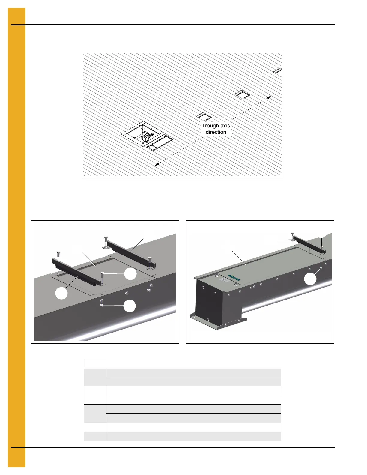
5. Layout the aeration floor and cut the opening around the gates (43). Refer to Page 55 for rough
opening dimensions. (See Figure 4I.)
Figure 4I
6. Install two gate seal assemblies (42) on each intermediate gate (43). Install one gate seal assembly
(42) on the center gate (44). Secure to trough with the supplied hardware (1 and 13). The aeration
floor is not shown for clarity. (See Figure 4J.)
Figure 4J Intermediate Gate Figure 4K Center Gate
Ref # Description
1
3/8" x 3/4" Bolt Grade 5 UNC Plated (2) (per Center Gate)
3/8" x 3/4" Bolt Grade 5 UNC Plated (4) (per Intermediate Gate)
13
3/8" Serrated Flange Nut (2) (per Center Gate)
3/8" Serrated Flange Nut (4) (per Intermediate Gate)
42
Gate Seal Assembly (2021) (1) (per Center Gate)
Gate Seal Assembly (2021) (2) (per Intermediate Gate)
43 Intermediate Gate
44 Center Gate
 Loading...


