HTTP://WWW.HOMBI.RU
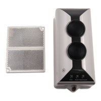
C-9105R
Conventional Reflective Beam Detector
Installation and Operation Manual The Intelligent Solution
16
detector to align the light beam until Green LED is lit
continuously, showing that the light received by the detector is
strong. Then stop regulating and enter step 4). If Green LED
illuminates continuously, it means the received light is quite
strong, you can go straight to step 4).
Note: Observe the detector’s optical pathway carefully to
ensure that the received light signal is reflected by the
reflector rather than by obstructions like wall, ceiling or
pillar. If uncertain, verify by covering the reflector with
opaque objects.
4) Put on the top cover gently; screw the two bolts on the cover.
5) The green LED illuminates continuously. Put the magnet of
commission tool close to the zone where marked M until Yellow
LED illuminates continuously, then remove the commission tool
quickly and make sure there is no obstruction on the optical
pathway. About 5 seconds later, the detector begins to adjust
automatically. Yellow LED flashing means weak light, Green
LED flashing means strong light. Ten seconds later, If Red LED,
Yellow LED and Green LED flash alternately, this means the
detector failed to adjust automatically and cannot enter normal
monitoring state. Please open the detector’s top cover and do
adjustment again from step 2). If Yellow LED and Green LED
illuminate no more, and Red LED flashes periodically, this
means the detector is at the best position and has entered
normal monitoring state. The commission is finished.
2. Fire Alarm Test
After the detector has been in normal monitoring state for 20s,
cover the receiving window and emitting window with the IR
HTTP://GSTRU.RUE-MAIL: hombi@hombi.ru
 Loading...