26 www. gsw-wh .com 328765-000
STRAP (FIELD
SUPPLIED)
COMBUSTION
AIR
COMBUSTION
AIR
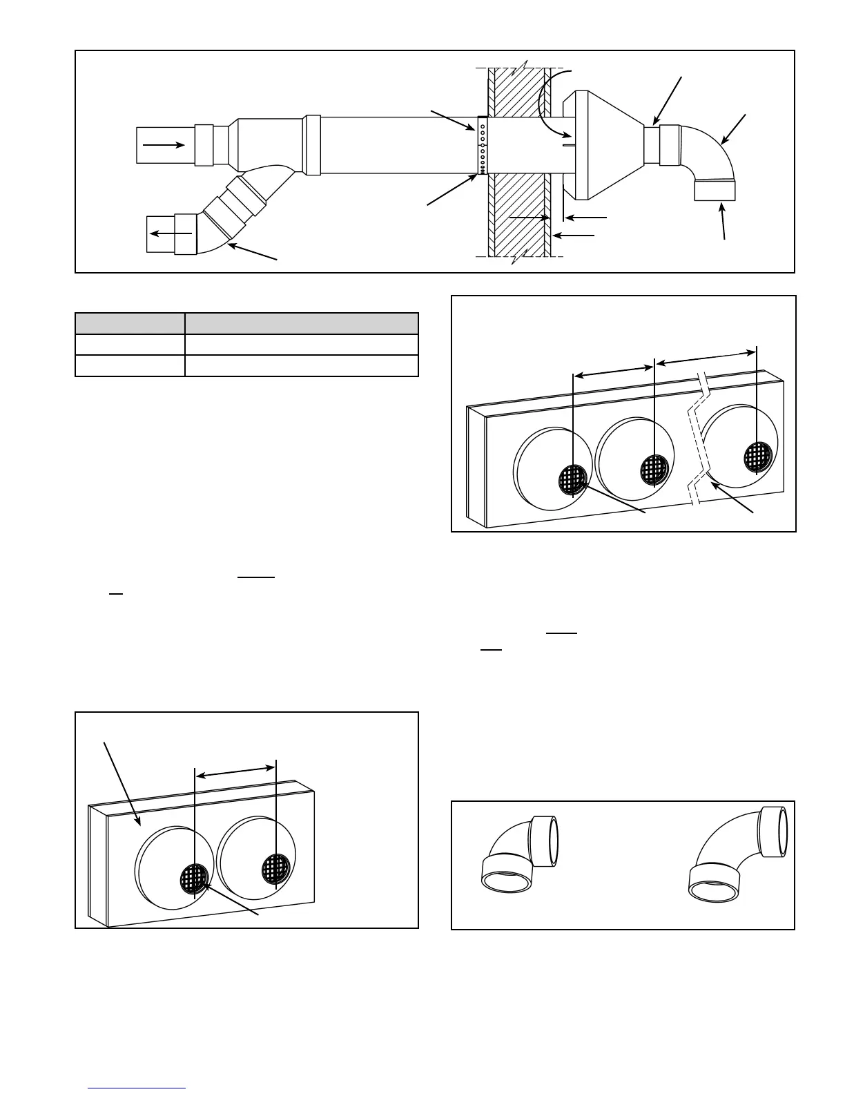
ORIENTATION OF EXHAUST PIPING AND COMBUSTION AIR PIPING RELATIVE
TO EACH OTHER MAY BE VERTICAL (AS SHOWN) OR AT ANY OTHER ANGLE
TO SUIT THE INSTALLATION.
ELBOW (FIELD
SUPPLIED)
SLOPE 6mm (1/4”)
OVER 1.5m (5’)
SCREEN INSIDE
EXHAUST
25mm (1”) MAXIMUM
WALL
90° ELBOW
(SEE LOCAL
CODES)
PIPE NIPPLE (USE
WITH ELBOW)
Figure 23
VENT DIA. P/N
2” 9008586005
3” 9006328005
Table 2
Figure 23 illustrates the concentric vent kit for a horizontal
(side wall) installation. To prevent rain water from entering
the exhaust outlet, slope the vent kit at a downward pitch
of 6mm (1/4”) per 1.5m (5’) away from the inside wall.
Ensure the combustion air intake location is above the
anticipated snow level.
Multiple Concentric Vent Installations
When two concentric vent kits are being installed, the
vent hood centers shall be either less than 240mm (9.5”)
apart or more than 1.1m (43.5”) apart. Spacings between
240mm (9.5”) and 1.1m (43.5”) are not allowed due to the
possibility of exhaust cross circulation (see Figure 24).
When more than 2 kits are installed only 2 of them shall be
less than 240mm (9.5”) apart. Never install 3 termination
kits together less than 240mm (9.5”) apart (see Figure 25).
240mm (9.5”) MAX OR
1.1m (43.5”)
MIN
WALL
SCREEN
NOTE: IF AN
ELBOW IS
REQUIRED
BY LOCAL
CODES
INSTALL
SCREEN
IN ELBOW
INSTEAD OF
CONCENTRIC
VENT
EXHAUST.
Figure 24
1.1m (
43.5”)
MIN.
240mm
(9.5”)
MAX..
WALL
NOTE: IF AN ELBOW IS REQUIRED BY
LOCAL CODES INSTALL SCREEN IN ELBOW
INSTEAD OF CONCENTRIC VENT EXHAUST.
SCREEN
Figure 25
Vent Pipe Length
The maximum allowable pipe lengths for air intake and
exhaust are listed in Table 3. The specifi ed maximum
lengths are for each of the intake and exhaust systems
and not for the combined lengths of both systems. In
addition, each system requires a 45° long sweep elbow
termination with a restrictive screen. Minimum pipe length
is 0.914m (3’) with a minimum of one 90° elbow per side
(intake and exhaust).
1. Determine termination type and pipe size.
2. Determine number of elbows in vent system. Do not
include termination elbow. Calculate the maximum
equivalent length of the exhaust and air intake system.
90° LONG SWEEP ELBOW
(LESS RESTRICTIVE)
90° SHORT SWEEP ELBOW
(MORE RESTRICTIVE)
Figure 26