18
Power cable from
operator (master) arm
SWITCH
STALL FORCE
M
I
N
M
A
X
MASTER INPUTS
GRN
WHT
BLUE
BRN
ORG
RED
BLK
GRN
BLK
RED
RECEIVER
COM COM
CYCLE
CLOSE
SAFET
Y
EXI
T
OPEN
SHADOW
LOOP
CLOSE
EDGE
OPEN
EDGE
J11
J8J5J13
J12
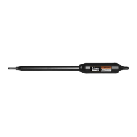
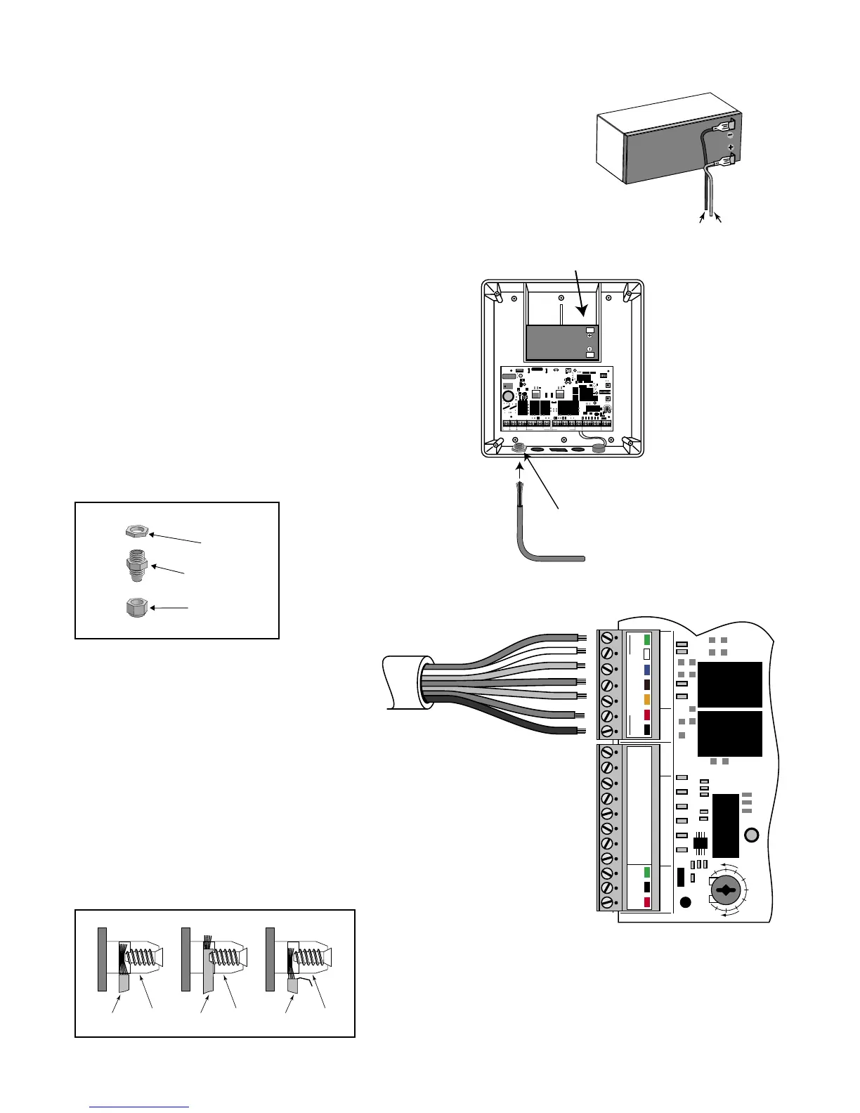
Step 15
Strip approximately
3
/16" of insulation from each wire
of the operator power cable. Twist each exposed wire
tightly (there are seven [7] wires inside the power cable
sheath). Loosen sealing nut on strain relief hub at
bottom of control box. Insert power cable into control
box through strain relief. Thread approximately 6" of the
power cable into the control box and retighten sealing nut
until the power cable locks into place.
Step 16
Insert the stripped operator power cable wires into
the appropriate terminals on the OPERATOR
terminal block. The green wire should be inserted
into the GRN terminal, the blue wire into BLU, the
orange wire into ORG, black wire into BLK, and
the red wire into the RED terminal.
Tighten the set screws against the end of the wires.
A dab of petroleum jelly on each terminal will help
prevent corrosion. Do not overtighten.
Correct
Wrong Wrong
Wire
Terminal
Block
Terminal
Block
Terminal
Block
Wire
Wire
Connecting Operator Power Cable
Sealing Nut
Hub
Lock Nut
Strain Relief
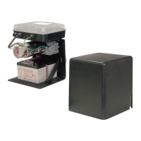
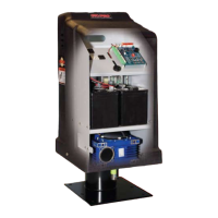
Step 14
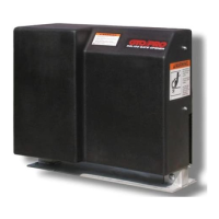
Make sure the control box power switch is in the OFF position.
The ON/OFF Switch is located on the bottom of the control box.
Remove the control box cover and slide the battery into position
with its terminals to the RIGHT (see illustration). Connect the
BLACK battery wire to the NEGATIVE (–) battery terminal.
Connect the RED battery wire to the POSITIVE (+) terminal. Pay
close attention to the color of the wires. If the wires are connected
incorrectly, the control board may be damaged. NEVER insert
the battery with the terminals to the left.
RED wire to POSITIVE (+) terminal
BLACK wire to NEGATIVE (—) terminal
RED
BLACK
Operator Power Cable
12 V Battery (Included)
Strain Relief
1
ON
2 3 4 5 6 7
1
ON
2 3 4
15
18VAC RECEIVER
BAT
+
SWITCH
FUSE
ALARM
SWITCH
DUAL
MODE
S
SET
LIMI
T
LEARN
TRANSMITTE
R
MODE
S
ON
OF
F
ON
OF
F
1 2 3 4 5 6 7
1 2 3 4
BAT
–
SOLAR RELAY OUT SLAVE INPUTS
GRN WHT BLUE BRN ORG RED BLKNC RLY-COM NO
MASTER INPUTS
GRN WHT BLUE BRN ORG RED BLK COM COM
CYCLE
CLOS
E
SAFET
Y
EXIT
/
OPEN
SHADOW
LOOP
CLOS
E
EDGE
OPEN
EDGE
BLKGRN RED
+–~~
12'
10'
8'
14'
16'
GATE LENGT
H
800-543-GATE
www.gtoinc.com
GTO, Inc.
3121 Hartsfield Rd
Tallahassee, FL 32303